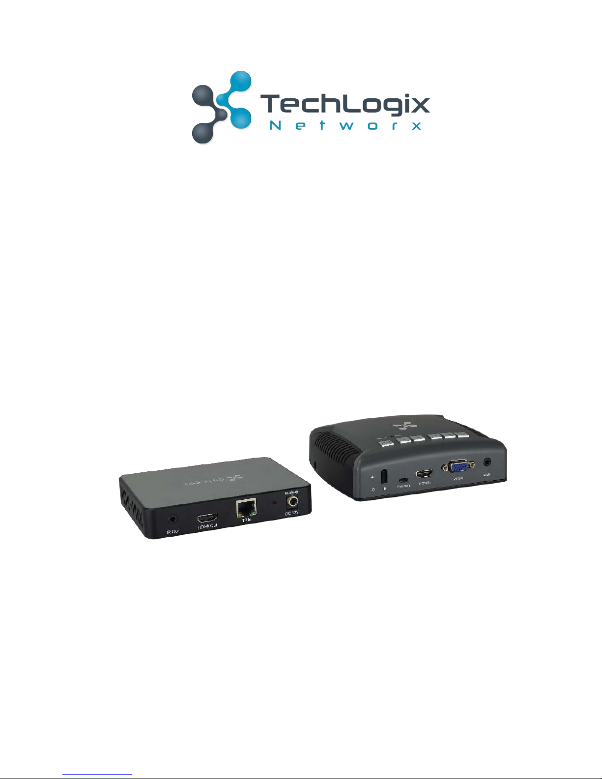
Techlogix TL-SMP-HDV Manuel utilisateur

User Manual
TL-SMP-HDV
Collaboration Hub
All Rights Reserved
Version: TL-SMP-HDV_170104

www.tlnetworx.com
TL-SMP-HDV User Manual
Preface
Read this user manual carefully before using this product. Pictures shown in this manual
is for reference only, different model and specifications are subject to real product.
This manual is only for operation instruction only, not for any maintenance usage.
Trademarks
Product model and logo are trademarks. Any other trademarks mentioned in this manual
are acknowledged as the properties of the trademark owner. No part of this publication
may be copied or reproduced without the prior written consent.
FCC Statement
This equipment generates, uses and can radiate radio frequency energy and, if not
installed and used in accordance with the instructions, may cause harmful interference
to radio communications. It has been tested and found to comply with the limits for a
Class B digital device, pursuant to part 15 of the FCC Rules. These limits are designed to
provide reasonable protection against harmful interference in a commercial installation.
Operation of this equipment in a residential area is likely to cause interference, in which
case the user at their own expense will be required to take whatever measures may be
necessary to correct the interference.
Any changes or modifications not expressly approved by the manufacture would void
the user’s authority to operate the equipment.

www.tlnetworx.com
TL-SMP-HDV User Manual
SAFETY PRECAUTIONS
To insure the best from the product, please read all instructions carefully before using
the device. Save this manual for further reference.
l Unpack the equipment carefully and save the original box and packing material for
possible future shipment
l Follow basic safety precautions to reduce the risk of fire, electrical shock and injury
to persons.
l Do not dismantle the housing or modify the module. It may result in electrical shock
or burn.
l Using supplies or parts not meeting the products’ specifications may cause damage,
deterioration or malfunction.
l Refer all servicing to qualified service personnel.
l To prevent fire or shock hazard, do not expose the unit to rain, moisture or install
this product near water.
l Do not put any heavy items on the extension cable in case of extrusion.
l Do not remove the housing of the device as opening or removing housing may
expose you to dangerous voltage or other hazards.
l Install the device in a place with fine ventilation to avoid damage caused by
overheat.
l Keep the module away from liquids.
l Spillage into the housing may result in fire, electrical shock, or equipment damage. If
an object or liquid falls or spills on to the housing, unplug the module immediately.
l Do not twist or pull by force ends of the optical cable. It can cause malfunction.
l Do not use liquid or aerosol cleaners to clean this unit. Always unplug the power to
the device before cleaning.
l Unplug the power cord when left unused for a long period of time.
l Information on disposal for scrapped devices: do not burn or mix with general
household waste, please treat them as normal electrical wastes.

www.tlnetworx.com
TL-SMP-HDV User Manual
Contents
1. Introduction ................................................................................................................. 1!
1.1 Introduction to TL-SMP-HDV ............................................................................ 1!
1.2 Features ............................................................................................................. 1!
1.3 Package List ........................................................................................................ 2!
2. Panel Description ......................................................................................................... 3!
2.1 Transmitter ......................................................................................................... 3!
2.2 Receiver .............................................................................................................. 5!
3. System Connection ...................................................................................................... 6!
3.1 Usage Precautions .............................................................................................. 6!
3.2 System Diagram .................................................................................................. 6!
3.3 Connection Procedure ........................................................................................ 6!
4. CEC Control ................................................................................................................. 8!
5. IR Control .................................................................................................................... 9!
6. Specification .............................................................................................................. 10!
7. Panel Drawing ............................................................................................................ 12!
7.1 Transmitter ....................................................................................................... 12!
7.2 Receiver ............................................................................................................ 12!
8. Troubleshooting & Maintenance ................................................................................ 13!
9. After-sales Service ..................................................................................................... 14!

1
www.tlnetworx.com
TL-SMP-HDV User Manual
1. Introduction
1.1 Introduction to TL-SMP-HDV
The TL-SMP-HDV is a Collaboration Hub consists of Transmitter and Receiver.
HDBaseT technology is used to transmit high-resolution 1080p/4K signal from
Transmitter to the Receiver over CAT5e/6a/7 cable at a distance of up to 70/40m.
The Transmitter features one HDBaseT output, one built-in IR sensor, one HDMI input,
and one VGA input with built-in VGA scaler function; the Receiver supports one
HDBaseT input, one IR output and one HDMI output.
1.2 Features
l HDMI video resolution up to 4Kx2K @30Hz 4:4:4, compliant with HDMI1.4&
HDCP1.4.
l VGA input video resolution up to 1920x1200 @60Hz 4:4:4.
l When VGA video is selected as input, the output resolution will be enhanced to
1080p automatically to assure high-definition image.
l Maximum transmission distance is 70m for 1080p and 40m for 4Kx2K over
CAT5e/6a/7 cable.
l The Transmitter are powered by the Receiver by PoH technology.
l Support front panel button control, and the buttons can replace the key functions of
IR Remote based on IR learning function.
l Support manual CEC control.
l Support Micro USB online firmware update.
l Support Hot-plug.
l LED indicators show work status.

2
www.tlnetworx.com
TL-SMP-HDV User Manual
1.3 Package List
l 1 x Transmitter
l 1 x Receiver
l 1 x IR Emitter
l 8 x Rubber feet
l 1 x Iron Plate (mounted in the bottom of Transmitter)
l 2 x Mounting Ears with 2 screws (for Receiver)
l 1 x Power Adapter (12VDC 2A)
l 1 x User Manual
Note: Confirm all the accessories are included, if not, please contact with the dealers.

3
www.tlnetworx.com
TL-SMP-HDV User Manual
2. Panel Description
2.1 Transmitter
No.
Name
Description
①
Power LED
Red when powered on.
②
Built-in IR Sensor
Receive the IR control signal sent from IR remote.
③
Firmware
Micro USB port, used for firmware update.
Firmware updated need auxiliary equipment, please
contact with our after-sales department for more details.
④
HDMI In
Connect with HDMI source.
⑤
VGA In
Connect with VGA source.
⑥
Audio
Auxiliary audio input for VGA video.
⑦
HDMI LED
The LED will turn green once the HDMI input is selected.
⑧
VGA LED
The LED will turn green once the VGA input is selected.
⑨
SOURCE
Input source selector, press this button to select input
source between HDMI and VGA.
⑩
DISPLAY
ON:
l Customized button based on IR control.
l Press it to turn on display device via built-in CEC
123456
910 11
12 13
78
Bottom Side

4
www.tlnetworx.com
TL-SMP-HDV User Manual
function.
OFF:
l Customized button based on IR control.
l Press it to turn off display device via built-in CEC
function.
⑪
VOLUME
UP:
l Customized button based on IR control.
l Press it to turn up the volume of display device via
built-in CEC function.
DOWN:
l Customized button based on IR control.
l Press it to turn down the volume of display device
via built-in CEC function.
MUTE:
l Customized button based on IR control.
l Press it to mute the display device via built-in CEC
function.
⑫
TP Out
Connect with the TP In socket on the Receiver via
CAT5e/6a/7 cable. Support unidirectional PoH.
⑬
DIP
Switcher(IR/CEC)
IR control mode: The buttons (ON, OFF, UP, DOWN and
MUTE) need to learn the functions of IR remote before
using.
CEC control mode: The buttons (ON, OFF, UP, DOWN,
and MUTE) can be used to control display device directly
based on CEC function.

5
www.tlnetworx.com
TL-SMP-HDV User Manual
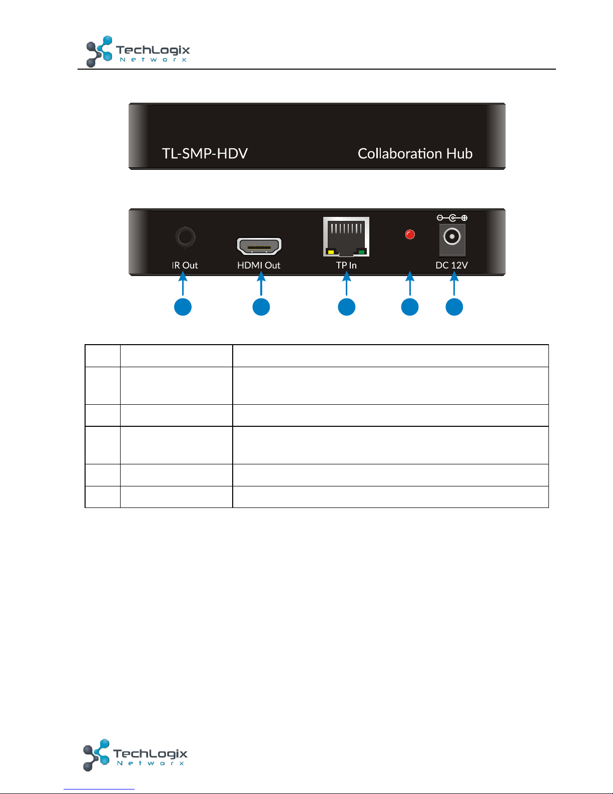
2.2 Receiver
No.
Name
Description
①
IR Out
Connect with IR Emitter to send infrared signal to control
display device.
②
HDMI Out
HDMI output port, connect to display device.
③
TP In
Connect with the TP Out socket on the Transmitter via
CAT5e/6a/7 cable. Support unidirectional PoH.
④
Power LED
Red when power on.
⑤
DC 12V
Power port, plug a DC 12V power adapter into this port.
123 5
4

6
www.tlnetworx.com
TL-SMP-HDV User Manual
3. System Connection
3.1 Usage Precautions
l
Verify all components included with the product are present before installation
l
System should be installed in a clean environment and has a prop temperature
and humidity.
l
If the product will be permanently mounted to a surface, attach the included
mounting ears with the supplied screws.
l
If the products will be sitting on a shelf, attach the included Plastic cushions to
the bottom of the unit.
l
All of the power switches, plugs, sockets and power cords should be insulated
and safe.
l
Turn off power and disconnect the audio/video equipment by following the
manufacturer’s instructions.
3.2 System Diagram
3-1 System Diagram
3.3 Connection Procedure
1. Verify all components included with the Collaboration Hub are present before
installation.
2. The included rubber feet should be mounted on the bottom surface.
HDMI:
VGA:
IR:
HDBaseT:
AUDIO:
IR
Emitter
DVD
HDTV
TV Remote
Transmitter
Bottom Side
Receiver
Laptop
Table des matières
Autres manuels Techlogix Changer

Techlogix
Techlogix TL-SM3X1-HDV Manuel utilisateur

Techlogix
Techlogix TL-4X1-HD2 Manuel utilisateur

Techlogix
Techlogix TL-5X1-HDV Manuel utilisateur

Techlogix
Techlogix TL-SM3X1-HD Manuel utilisateur

Techlogix
Techlogix TL-6X1-HDV Manuel utilisateur

Techlogix
Techlogix TL-SM3C-HDV Manuel utilisateur

Techlogix
Techlogix TL-NS24R2S-POE Manuel utilisateur