Tech West ELITE Series Manuel

2625 N. Argyle Ave. • Fresno, CA 93727
(559) 291-1650 • (800) 428-7139 • FAX (559) 348-9677
T
ECH
W
EST
I
NC.
Manufacturers of Dental Vacuum
and Air Systems
ELITE SERIES
ROCKY COMPRESSOR
INSTALLATION
AND SERVICE
MANUAL
Revised 12-18

ELITE SERIES
ROCKY COMPRESSOR
INSTALLATION AND SERVICE MANUAL
This manual is for the installation and service of Tech West’s Elite Series Rocky Compressors.
CONTENTS
Installation
Location Requirements 2
Figure 1: Wire and Breaker Sizes 2
Elite Series Rocky Installation Steps 3
Elite Series Rocky Compressor Connections 4
Elite Series Rocky Start Up 5
Elite Series Rocky Maintenance 6
Elite Series Rocky Compressor Motor Assembly Breakdown 7-8
Coalescing Filter Assembly Breakdown 9
Tank Breakdown 10
Desiccant Dryer Parts Breakdown 11
Gauge and Moisture Indicator Assembly Breakdown 12
Wiring Diagram, 115V 13
Wiring Diagram, 230V 14
Dual Elite Series Rocky Compressor Assembly 15
TROUBLE SHOOTING
Dual Rocky Compressor Trouble Shooting 18-19
Air Line Sizing Chart 22
Maintenance Schedule 23
Maintenance/Service and notes 24-25
1

ELITE SERIES ROCKY COMPRESSOR
INSTALLATION
1. ROCKY COMPRESSOR LOCATION REQUIREMENTS
The Elite Series Rocky Compressor location should be level, accessible and well ventilated.
If the Elite Series Rocky Compressor will be located in a confined space, provide adequate ventilation.
Electrical
(1) Line voltage must be within the limits of Figure 1 below. (Install a “buck-boost
transformer” if line voltage is not between these values.) Circuit breaker switches must
be 20 amp voltage.
(2) Local code may require you to provide a quick disconnect (safety switch) for the
compressor.
(3) See Figure 1 below for breaker size and line voltage.
CAUTION - Voltage must be 208/240 V or motor damage may occur.
CAUTION - Voltage must be 110/120 V or motor damage may occur.
2
Figure 1: Recommended Wire and Breaker Size
Dual Head Compressors
Model Voltage Amperage Wire Size Recommended
(Gauge) Breaker Size
ACOR2D1 110/120 11 12 20
ACOR2D2 208/230 7.6 12 20
ACOR2D1Q 110/120 11 12 20
ACOR2D2Q 208/230 7.6 12 20

ELITE SERIES ROCKY COMPRESSOR
INSTALLATION
2
2. INSTALLATION STEPS
This dental compressor should only be installed by qualified personnel. Should any questions arise
during the installation, call Tech West Technical Support between the hours of 7:00 a.m. to 4:00 p.m.
(Pacific Standard Time).
Place the compressor in a clean, dry, well ventilated area, on a solid, level surface. Consider sound
level and insulate as needed. Be sure that adequate ventilation is available as the compressor is air
cooled. Ambient temperature in the equipment room should be within the temperature range of 40
degrees Fahrenheit minimum to 104 degrees Fahrenheit maximum.
(a) Check the shipping carton for damage. This could detect damage to the unit which might
otherwise be overlooked. Remove cardboard shipping carton.
(b) Remove the Oilless Compressor from its shipping skid. Inspect the unit for damage.
Oilless Compressors are shipped bolted to a pallet. This pallet is intended for shipping only
and should be discarded.
(c) Remove installation kit attached to pallet. It should contain the following:
(4) Isolation Feet
(1) Alternate Air Hookup Hose
(1) 5’ Flexible Air Hose
(d) Install isolation feet on tank legs.
(e) Move compressor into place and make sure it is completely level.
(f) Wiring instructions:
(1) Have all electrical connections made by qualified personnel only. All connections
should be in accordance with local codes.
(2) Use the chart on page 1 to help determine the proper line and breaker size for
the unit that is being installed.
(g) Install the air line from the compressor tank to the building supply.
(h) Install the 1” flex alternate air hose from the compressor to a fresh air supply.
3

4
ELITE SERIES ROCKY COMPRESSOR
INSTALLATION
2
3. CONNECTIONS
Figure 2
Dryer Purge
Connection
Electrical Connection to
disconnect and electrical panel
(110 v / 220 v)
Alternate Air
Connection
to fresh air supply
Air Out
Connection to building
supply line

5
ELITE SERIES ROCKY COMPRESSOR
INSTALLATION
2
4. SAFETY PRECAUTIONS
• Keep fingers, foreign objects and clothing free from rotating parts and do not touch hot surfaces.
• Never attempt to service an operating unit.
• Isolate unit from system pressure and relieve backpressure before servicing
• Disconnect all power before servicing. The thermal protector in single phase motors
automatically starts motor when device resets.
USE OF THIS PRODUCT IN OR NEAR EXPLOSIVE ATMOSPHERES, OR FOR
PUMPING MIXTURES OTHER THAN ATMOSPHERIC AIR MAY CAUSE AN
EXPLOSION OR FIRE, RESULTING IN PERSONAL INJURY OR DEATH.
2
5. START-UP STEPS
(a) Make sure the shut-off valve from the compressor tank is closed.
(b) Turn the breaker from the panel to the “ON” position.
(c) Turn power “ON” from the toggle switch on the compressor. Compressor should run quietly
and vibration free. The storage tank should start to build pressure.
(d) The compressor will run until the pressure gauge reads 105 psi. The compressor then will
automatically shut off and the dryer will purge with a quick blast of air.
(e) Using soapy water, check the compressor plumbing hook ups for leaks. Repair leaks if needed.
(f) Pressure test the entire plumbing system for leaks. Use the storage tank pressure gauge to
monitor a pressure drop. After the plumbing system has been pressurized for 30 minutes,
re-check the gauge for pressure drop. If there is a drop in pressure, find and repair all leaks
in the office plumbing.
(g) Complete and mail in the warranty card for the compressor within ten days of installation.
AIR LEAKS ARE THE MAIN CAUSE OF COMPRESSOR FAILURES.

6
7. PERIODIC SERVICING
MONTHLY SERVICING
(a) Remove the purge bucket and empty as needed
(b) Crack the drain petcock on the bottom of the storage tank to check for water and drain if needed.
(c) Check moisture indicator to see that it is still “BLUE”. If it is pink, it is time to service the air dryer.
(d) Check pump-up times of the compressor.
(e) Check intake air supply filters. Replace filters as needed.
YEARLY SERVICING
(a) Repeat all of the monthly servicing.
(b) Replace the alternate air filter. (Part #: TIF-100)
(c) Check the coalescing filter and change if needed. (Part #: CFEO-375)
ELITE SERIES ROCKY COMPRESSOR
INSTALLATION
2
6. GENERAL SERVICE INFORMATION
For parts and service on Rocky series products contact the nearest authorized Tech West distributor. To
expedite appropriate service, be prepared to provide the unit model number, identification number,
and serial number found on the nameplate located on the front of the unit switch plate.
Component life operating at continuous duty & maximum pressure will shorten the life of the rings
and skirts. It is difficult to predict due to many conditions which directly influence wear. Some of
these conditions may include ambient air temperature, air cleanliness, operating pressure, piston
stroke on the particular model being utilized, duty cycle, maintenance of filters, etc.
Because of these various factors it is appropriate to generalize on component wear life and choose
some conservative estimates for most standard applications.
With these conditions in mind, we recommend the following preventative maintenance schedule.
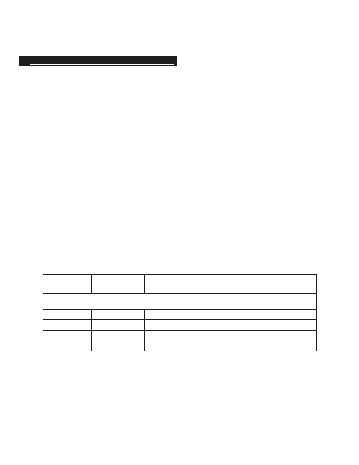
RECOMMENDED MAINTENANCE
FOR ROCKY MODELS
Minor Service Kits, Piston Cups & Valves, Skirts, Etc.
Major Replacement Kit, Piston & Rod Assemblies
Replace inlet Filter
HOURS
Cont. Duty
Maximum Pressure
8,000 Hours
12,000 Hours
4,000 Hours
TIME
Based on 100%
Duty Cycle
12 months
18 months
6 months

9
ROCKY FILTER ASSEMBLY
1
2
3
KEY PART NO. DESCRIPTION UNIT
1 CFAO-375 COALESCING FILTER ASSEMBLY 3/8 1
2 CFEO-375 COALESCING FILTER ELEMENT 3/8 1
3 CFBP-375 COALESCING FILTER BOWL 1

10
ROCKY REAR VIEW TANK ASSEMBLY AND PARTS LIST
KEY PART NO. DESCRIPTION UNIT
1 EDT-100 REPLACEMENT DESICANT CARTRIDGE - ELITE 1
2 EPT-100 ELITE PURGE TANK 1
3 ETAR-R ELITE TANK ANGLE ROCKY - REAR 1
4 ETHR ELITE TANK HANDLE ROCKY 2
5 EPCB ELITE PRECOOLER BRACKET 2
6 CFB-P COALESCING FILTER BRACKET 1
7 CFAO-375 COALESCING FILTER ASSEMBLY 1
8 ERPCM ELITE ROCKY PRECOOLER MOUNT 1
9 DPC-1E ELITE PRECOOLER - SINGLE 1
10 ETAR-F ELITE TANK ANGLE ROCKY - FRONT 1
11 ERMM ELITE ROCKY MOTOR MOUNT 1
12 CF-115-230E ELITE COOLING FAN - DUAL VOLTAGE 2
13 EAAR ELITE ALTERNATE AIR - ROCKY 1
1
3
2
4
5
7
8
9
6
10 11
12
13

11
ROCKY DESICCANT AIR DRYER ASSEMBLY
KEY PART NO. DESCRIPTION UNIT
1 DSV-115 115V PURGE SOLENOID VALVE 1
2 DSV-230 230V PURGE SOLENOID VALVE 1
3 AS-500 1/2 FILTER ASSY 1
4 EDC-100 REPLACEMENT DESSICANT TANK 1
5 MV-250 METERING VALVE 1
6 SN-250-CL STAINLESS STEEL NIPPLE 1/4 3
7 FE-4-6 FLAIR FITTING 1/4 X 3/8 1
8 BV-250 BALL VALVE 1/4 1
9 BT-250 BRASS TEE 1/4 2
10 FPH-375 CLEAR PURGE HOSE PER FOOT
11 MSD-100 MOLECULAR-SIEVE 1 LB 2LBS
12 MSD-200 ACTIVATED ALUMINA 1 LB 2LBS
13 CV-250D 1/4 CHECK VALVE 1
4
3
5
12
11
INSIDE
TANK
ELEMENT
Ce manuel convient aux modèles suivants
5
Table des matières
Autres manuels Tech West Compresseur d'air
Manuels Compresseur d'air populaires d'autres marques

Campbell Hausfeld
Campbell Hausfeld RP3300 Guide de démarrage rapide

Ingersoll-Rand
Ingersoll-Rand UP6 20 HP Manuel utilisateur

Hitachi
Hitachi EC99S Manuel de l'opérateur

Parkside
Parkside PKO 270 A1 Manuel utilisateur

Sullair
Sullair 185 Manuel utilisateur

Clas Ohlson
Clas Ohlson QIE-ZTH-15 Manuel utilisateur


