TeachLogic AR-960 Manuel utilisateur

AirLinkAirLinkAirLink
owner’s manual

notes
Date of Purchase:
Model Number:
Serial Number:
Notes:

contact
thank you
Hopefully this manual will
provide all the informa-
tion needed, however: our
customer service depart-
ment is readily available for
assistance.
4
AirLink
owner’s manual
Thank you for purchasing the AirLink, a stationary
line level audio transmission system. Whether the
need is to distribute audio to a distant location, to
an overflow crowd at a special event, or send the
announcer’s voice across the football stadium, Air-
Link can get the message across with ease. Tests
have been performed through multi-story build-
ings from basement to upper conference room,
from press box to a remote concession stand, and
to multiple locations using several receivers. Trans-
mission distance in excess of 500 feet has been
achieved in direct line of sight with absolute clarity
and rock solid connectivity.
This manual contains helpful information and in-
structions for setting up and operating the AirLink
system. The system is comprised of a stationary
transmitter and remote receiver. You simply plug a
line level program signal into the transmitter and it
will transmit the program to the remote receiver.
TeachLogic appreciates your confidence with your
purchase of our AirLink system. Be assured that
TeachLogic products are built to very high quality
standards, incorporate state of the art technology,
and employ the most advanced manufacturing
methodology.
Brian Van Waay
President
1•800•588•0018
sales@teachlogic.com
1•760•631•1283
www.teachlogic.com

safety instructions
Read Instructions
All safety and operation instructions should be
read before operating this TeachLogic product.
Retain Instructions
Safety and operating instructions should be kept
for future reference.
Water & Moisture
This product should not be operated
near water.
Heat Environment
Do not subject this product to excessive heat
conditions.
Power Source
This product must be connected to an AC power
source per the voltage input specified and marked
on the power supply.
Power Cord Caution
Power cable should be routed clear of foot traffic
and supported clear of kinking or abrasion.
Object Protection
Locate the operating unit so it will not be
subjected to falling objects or water entry.
Internal Service
User should not attempt to service this product.
All internal service must be accomplished by a
qualified technician.
Electric Shock
Do not adapt or modify the AC power plug thus
lifting the earth ground connection.
certifications
Listed
US CA
TeachLogic systems are
manufactured using lead-
free processes and are free
of materials harmful to the
environment. They conform
to the most stringent new
European guidelines for
consumer products (RoHS).
Recycle—Do not dispose
rechargeable batteries in
trash. Actually it is unlawful
to do so in CA,NY & ME.
Contact: Earth911.com
1-800-CLEANUP
Save our resources and
don’t contaminate.
Go Green
caution

transmitter
table of contents
Product Description.....................................................
Transmitter Panel Components...............................
Receiver Panel Components.....................................
Transmitter Setup Instructions.................................
Receiver Setup Instructions......................................
Operating the AirLink Router System....................
Troubleshooting.......................................................
Specifications...............................................................
Five Year Limited Warranty........................................
1
2
3
4
5
6
7–9
10
11
6
AirLink
owner’s manual

product description
The AirLink system is a wireless audio router that
transmits audio via an RF signal to a receiver. The
system is comprised of a transmitter base station
that transmits to a diversity receiver. The system
operates in the UHF range (640–664 MHz). The
system has 96 selectable preset channels. Trans-
mitter RF output is 40 mW.
The input to the transmitter is line level audio. Two
line level audio signals can be input and mixed in
the transmitter for a composite signal transmission.
The output level of each input can be adjusted and
turned “on/off”. The output of the unbalanced line
input can be monitored with a headset.
The receiver is a diversity receiver, meaning the
signal will be received by either of two receivers;
whichever has the best reception. Each receiver
has a half-wave antenna for extra sensitive recep-
tion. The output of the receiver is either a bal-
anced (XLR) or unbalanced (RCA) and is adjustable
from 0–700 mV.
1

front of ALS-960 transmitter
back of ALS-960 transmitter
Power Switch and LED
Output Gain Control for
Balanced Input
Transmit “on/off” for
Balanced Input
Output Gain Control for
Unbalanced Input
Transmit “on/off” for
Unbalanced Input
RF Transmission Indicator
(Yellow LED)
TNC Antenna Connector
Unbalanced Line Output
(Pre Fader)
Unbalanced Line Input
(Stereo RCA)
Balanced Line Level Input (XLR)
LCD Display: Channel # or
Frequency Readout
AF Transmission Indicator
(Orange LED)
Signal Peak Indicator (Red LED)
Channel Set: Lock/Unlock
Channel “Up/Down” Selector
Transmitter Module: “on/off”
and Master Gain
Headphone Volume
Headphone Output for
Unbalanced Input
Phantom Mic Power “on/off”, 5v
Microphone Input: Hi-z/
Condenser
DC Output: 10–15 volt
Power Input: 10–15 volt
2
STATIONARY TRANSMITTER
POWER
UHF-PLL
SET
TX AF LEVEL
OFFM AX VOL.
ALS-960
VOL.VOL.
LINE
TX.
ON ON
AUX
TX.
1413121110987654321
1
2
3
4
5
6
7
8
9
10
11
12
13
14
5
6
7
8
1
2
3
4
ANTENNA OFF
AUX LINE LEVEL
MIC IN
CONDENSER-—UNBAL.D C OUT
10~15V
5V
OFF/ON
BALANCED
OUTI N
L
R
L
R
DC IN
10~15V
87654321
AirLink
owner’s manual
2

3
front of DR-701 receiver
rear of DR-701 receiver
Power Switch and LED
RF Reception: Diversity A/B
Antenna (Red/Green LED)
LCD Display: Channel # or
Frequency Readout
AF Signal Present Indicator
(Green LED)
TNC connector for swivel
antenna “A”
Balanced Line Level Output:
0-700 mV (XLR)
Unbalanced Output: Switchable
mic/line level (1/4” phone)
Signal Peak Indicator (Red LED)
Channel Set: Lock/Unlock
Channel “Up/Down” Selector
Receiver Module: “on/off”
and Master Gain
Mic/Line Level switch for
unbalanced output
DC power input: 12–15 volt, 1A
TNC connector for swivel
antenna “B”
1
2
3
4
5
6
7
8
4
5
6
1
2
3
UHF-PLL
PRO. WIRELESS RECEIVER
POWER
UHF-PLL
SET
A/BR XA F
OFFM AX
87654321
DC OUT
12~15V/1A
LOW/HI
AF OUT
ANT. BANT. A
654321

transmitter
antenna installation
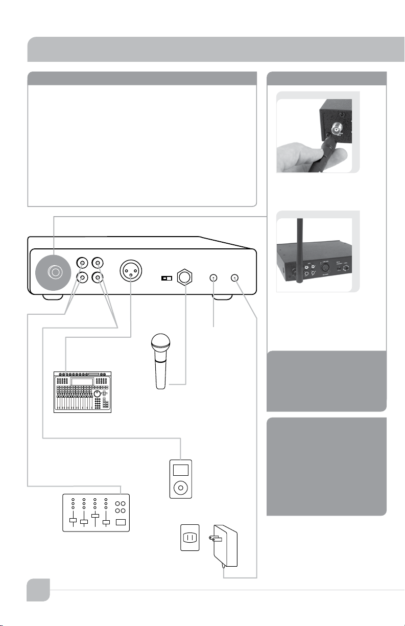
TRANSMITTER setup instructions
Locate transmitter (ALS-960) in vicinity of mixer
or other audio source.
Plug power supply into AC power outlet
Connect output from primary audio source to
transmitter to either:
Balanced Input: Shielded cable with XLR
Unbalanced Input: Shielded cable with RCA
connector (Mono or Stereo)
Connect alternate audio source to other input
•
•
•
•
•
•
Screw antenna into TNC
connector loosely.
Adjust antenna to straight
up vertical position.
Tighten connector to
snug fit.
104
Do not attempt to change
antenna orientation while
in tightened condition.
To extend the range of the
AirLink AR-960 system,
replace the antenna of the
transmitter with a periodic-
log antenna oriented in the
horizontal position.
OFF
AUX
MIC IN
CONDENSER-—UNBAL .DC OUT
10~15V
5V
OFF/ON
BALANCED
OUT IN
L
R
L
R
DC IN
10~15V
ANTENNA
MIXER
DIGITAL MUSIC PLAYER
POWER SUPPLY
RECORDER
MICROPHONE
caution
note
.DC OUT
10~15V
AirLink
owner’s manual
4
Transmitter
Ce manuel convient aux modèles suivants
1
Table des matières
Manuels Routeur réseau populaires d'autres marques

NETGEAR
NETGEAR FS526T - Switch Manuel utilisateur

Korenix
Korenix JetNet 5710G Series Manuel utilisateur

Automated Logic
Automated Logic ZN551 Manuel du propriétaire

Cisco
Cisco ASR 1000 Series Manuel de l'opérateur

EnGenius
EnGenius ESR-9710 Manuel utilisateur

Cisco
Cisco 805 Series Instructions d'utilisation et de sécurité