TE HumPRC Series Manuel utilisateur

HumPRCTM Series
Master Development System
User's Guide

Warning: Some customers may want Linx radio frequency (“RF”)
products to control machinery or devices remotely, including machinery
or devices that can cause death, bodily injuries, and/or property
damage if improperly or inadvertently triggered, particularly in industrial
settings or other applications implicating life-safety concerns (“Life and
Property Safety Situations”).
NO OEM LINX REMOTE CONTROL OR FUNCTION MODULE
SHOULD EVER BE USED IN LIFE AND PROPERTY SAFETY
SITUATIONS. No OEM Linx Remote Control or Function Module
should be modified for Life and Property Safety Situations. Such
modification cannot provide sufficient safety and will void the product’s
regulatory certification and warranty.
Customers may use our (non-Function) Modules, Antenna and
Connectors as part of other systems in Life Safety Situations, but
only with necessary and industry appropriate redundancies and
in compliance with applicable safety standards, including without
limitation, ANSI and NFPA standards. It is solely the responsibility
of any Linx customer who uses one or more of these products to
incorporate appropriate redundancies and safety standards for the Life
and Property Safety Situation application.
Do not use this or any Linx product to trigger an action directly
from the data line or RSSI lines without a protocol or encoder/
decoder to validate the data. Without validation, any signal from
another unrelated transmitter in the environment received by the module
could inadvertently trigger the action.
All RF products are susceptible to RF interference that can prevent
communication. RF products without frequency agility or hopping
implemented are more subject to interference. This module does have
a frequency hopping protocol built in, but the developer should still be
aware of the risk of interference.
Do not use any Linx product over the limits in this data guide.
Excessive voltage or extended operation at the maximum voltage could
cause product failure. Exceeding the reflow temperature profile could
cause product failure which is not immediately evident.
Do not make any physical or electrical modifications to any Linx
product. This will void the warranty and regulatory and UL certifications
and may cause product failure which is not immediately evident.
!

Table of Contents
1 Introduction
2 Ordering Information
3 HumPRCTM Series Transceiver Carrier Board
3 HumPRCTM Series Transceiver Carrier Board Objects
3 HumPRCTM Series Transceiver Carrier Board Pin
Assignments
4 Programming Dock
4 Programming Dock Objects
5 Remote Control Demo Board
5 Remote Control Demo Board Objects
6 Prototype Board
6 Prototype Board Objects
7 HumPRCTM Series Handheld Transmitter Evaluation
Board
8 Long-range Handheld Transmitter Button
Assignments
8 Initial Setup
10 Using the Programming Dock
11 Using the Remote Control Demo Board
13 Using the Prototype Board
16 Using the Handheld Transmitter Evaluation Board
17 Joining a Transmitter
18 The Development Kit Demonstration Software
25 Development Kit Demonstration Software Example
31 Carrier Board Schematic
32 Remote Control Demo Board Schematic
36 Programming Dock Board Schematic
40 Prototype Board Schematic
43 HumPRCTM Series Evaluation Board Schematic


– –
1
Introduction
The Linx HumPRCTM Series Remote Control Transceiver modules offer
a simple, efficient and cost-effective method of adding remote control
capabilities to any product. The Master Development System provides a
designer with all the tools necessary to correctly and legally incorporate the
module into an end product. The boards serve several important functions:
• Rapid Module Evaluation: The boards allow the performance of the
Linx HumPRC™ Series modules to be evaluated quickly in a user’s
environment. The development boards can be used to evaluate the
range performance of the modules.
• Application Development: A prototyping board allows the development
of custom circuits directly on the board. All signal lines are available on
headers for easy access.
• Software Development: A programming dock with a PC interface allows
development and testing of custom software applications for control of
the module.
• Design Benchmark: The boards provide a known benchmark against
which the performance of a custom design may be judged.
Includes 3 Carrier Boards, 2 PRC Demo Boards, 1 Programming Dock, 1
Prototype Board, 2 HumPRC™ Series transceivers, 1 PRC Long-Range
Handheld transmitter and accessories, 1 evaluation board, antennas,
batteries and USB cables.
HumPRCTM Master Development System
User's Guide
Figure 1: HumPRCTM Series Master Development System
– –
2
Ordering Information
Figure 2: Ordering Information
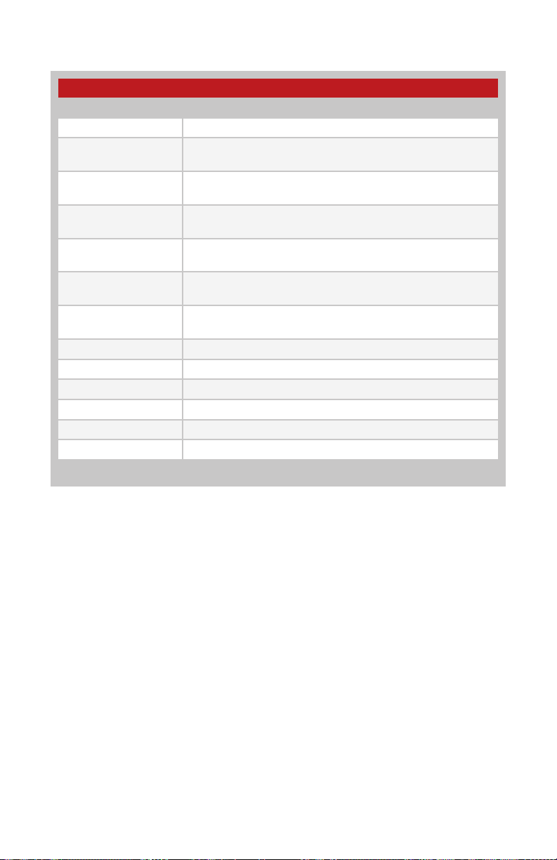
Ordering Information
Part Number Description
MDEV-***-PRC HumPRCTM Series Master Development System
HUM-***-PRC HumPRCTM Series Remote Control Transceiver, Castellation
Interface, External Antenna Connection
HUM-***-PRC-CAS HumPRCTM Series Remote Control Transceiver, Certified,
Castellation Interface, External Antenna Connection
HUM-***-PRC-UFL HumPRCTM Series Remote Control Transceiver, Certified,
Castellation Interface, U.FL Connector
EVM-***-PRC HumPRCTM Series Carrier Board, Not Certified, Through-Hole
Pin Interface, MMCX Connector for the Development System
EVM-***-PRC-CAS HumPRCTM Series Carrier Board, Certified, Through-Hole Pin
Interface, RP-SMA Connector
EVM-***-PRC-UFL HumPRCTM Series Carrier Board, Certified, Through-Hole Pin
Interface, U.FL Connector
OTX-***-HH-LR8-PRC HumPRCTM Long-Range Handheld Transmitter
MDEV-DEMO-RC-A Development System Remote Control Demo Board, Type A
MDEV-DEMO-RC-B Development System Remote Control Demo Board, Type B
MDEV-PGDOCK Development System Programming Dock
MDEV-PROTO Development System Prototype Board
CON-SOC-EVM EVM Module Socket Kit
*** = Frequency; 868, 900MHz

– –
3
HumPRCTM Series Transceiver Carrier Board Objects
1. HumPRCTM Series Transceiver
2. MMCX RF Connector
3. Dual Row Header
4. Single Row Header
HumPRCTM Series Transceiver Carrier Board
Figure 3: HumPRCTM Series Transceiver Carrier Board
1
2
34
HumPRCTM Series Transceiver Carrier Board Pin Assignments
Figure 4: HumPRCTM Series Transceiver Carrier Board Pin Assignments (Top View)
7 MODE_IND
9 CMD_DATA_IN
11 LATCH_EN
13 ACK_EN
15 CMD_DATA_OUT
17 VCC
19 C0
21 C1
23 NC
25 NC
27 NC
29 NC
31 NC
33 NC
35 NC
37 NC
GND 6
RESET 8
POWER_DOWN 10
NC 12
PAIR 14
LNA_EN 16
NC 18
PA_EN 20
NC 22
NC 24
NC 26
NC 28
NC 30
NC 32
NC 34
NC 36
41 S3
42 S4
43 S5
44 S6
45 S7
46 ACK_OUT
47 NC
48 NC
49 NC
50 NC
51 NC
52 NC
53 NC
54 NC
55 NC
56 NC
40 S2
39 S1
38 S0
ANTENNA 1 2-5 GND (RF Connector)

– –
4
Programming Dock
Programming Dock Objects
1. Carrier Board Socket
2. RP-SMA Antenna Connector
3. MODE_IND LED
4. Micro USB Connector
5. LCD Display
Figure 5: Programming Dock
2
3
4
5
1

– –
5
1
Remote Control Demo Board
Board BBoard A
Remote Control Demo Board Objects
1. Carrier Board Socket
2. RP-SMA Antenna Connector
3. Power Switch
4. MODE_IND LED
5. CONFIRM LED
6. PAIR button
7. Status Line Output LEDs
8. Status Line Input Buttons
9. 4 AAA Batteries (Not shown, on the back of the boards)
Figure 6: Remote Control Demo Board
1
2
3
4
5
6
7
8
1
2
3
4
5
6
7
8
– –
6
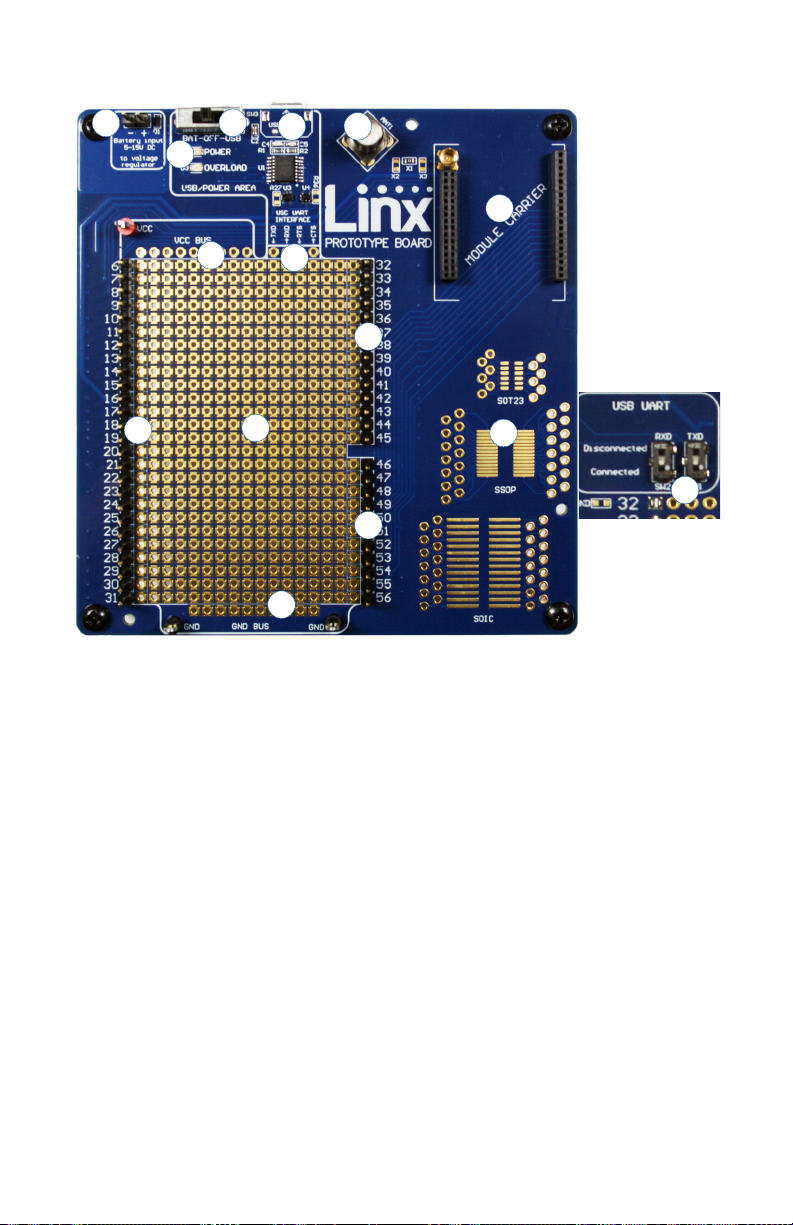
Prototype Board
Prototype Board Objects
1. Carrier Board Socket
2. RP-SMA Antenna Connector
3. Micro USB Connector
4. Power Switch
5. Power LED
6. External Battery Connection
7. Prototyping Area
8. 3.3V Supply Bus
9. Ground Bus
10. USB Interface Lines
11. Module Interface Headers
12. Standard IC Package Footprints
13. Command Data Interface Routing Switches (on back)
Figure 7: Prototype Board
4
1
2
3
10
6
7
8
11
5
9
11
11
13
12
Ce manuel convient aux modèles suivants
2
Table des matières
Manuels Matériel réseau populaires d'autres marques

Matrix Switch Corporation
Matrix Switch Corporation MSC-HD161DEL Manuel utilisateur

B&B Electronics
B&B Electronics ZXT9-IO-222R2 Manuel utilisateur

Yudor
Yudor YDS-16 Manuel utilisateur

D-Link
D-Link ShareCenter DNS-320L Manuel utilisateur

Samsung
Samsung ES1642dc Instructions d'utilisation

Honeywell Home
Honeywell Home LTEM-PV Instructions de montage


