Supermicro SC847 JBOD Manuel utilisateur

USER’S MANUAL
Revision 1.0c
SC847 JBOD
CSE-847E1C-R1K23JBOD CSE-847E2C-R1K23JBOD

The information in this User’s Manual has been carefully reviewed and is believed to be accurate.
The vendor assumes no responsibility for any inaccuracies that may be contained in this document,
makes no commitment to update or to keep current the information in this manual, or to notify any
person or organization of the updates. Please Note: For the most up-to-date version of this
manual, please see our web site at www.supermicro.com.
Super Micro Computer, Inc. ("Supermicro") reserves the right to make changes to the product
described in this manual at any time and without notice. This product, including software and
documentation, is the property of Supermicro and/or its licensors, and is supplied only under a
license. Any use or reproduction of this product is not allowed, except as expressly permitted by
the terms of said license.
IN NO EVENT WILL SUPERMICRO BE LIABLE FOR DIRECT, INDIRECT, SPECIAL, INCIDENTAL,
SPECULATIVE OR CONSEQUENTIAL DAMAGES ARISING FROM THE USE OR INABILITY TO
USE THIS PRODUCT OR DOCUMENTATION, EVEN IF ADVISED OF THE POSSIBILITY OF
SUCH DAMAGES. IN PARTICULAR, SUPERMICRO SHALL NOT HAVE LIABILITY FOR ANY
HARDWARE, SOFTWARE, OR DATA STORED OR USED WITH THE PRODUCT, INCLUDING THE
COSTS OF REPAIRING, REPLACING, INTEGRATING, INSTALLING OR RECOVERING SUCH
HARDWARE, SOFTWARE, OR DATA.
Any disputes arising between manufacturer and customer shall be governed by the laws of Santa
Clara County in the State of California, USA. The State of California, County of Santa Clara shall
be the exclusive venue for the resolution of any such disputes. Super Micro's total liability for all
claims will not exceed the price paid for the hardware product.
FCC Statement: This equipment has been tested and found to comply with the limits for a Class
A or Class B digital device pursuant to Part 15 of the FCC Rules. These limits are designed to
provide reasonable protection against harmful interference when the equipment is operated in
industrial environment for Class A device or in residential environment for Class B device. This
equipment generates, uses, and can radiate radio frequency energy and, if not installed and used
in accordance with the manufacturer’s instruction manual, may cause harmful interference with
radio communications. Operation of this equipment in a residential area is likely to cause harmful
interference, in which case you will be required to correct the interference at your own expense.
California Best Management Practices Regulations for Perchlorate Materials: This Perchlorate
warning applies only to products containing CR (Manganese Dioxide) Lithium coin cells. “Perchlorate
Material-special handling may apply. See www.dtsc.ca.gov/hazardouswaste/perchlorate”.
WARNING: This product can expose you to chemicals including
lead, known to the State of California to cause cancer and birth
defects or other reproductive harm. For more information, go
to www.P65Warnings.ca.gov.
!
Manual Revision 1.0c
Release Date: June 04, 2021 mk
Unless you request and receive written permission from Super Micro Computer, Inc., you may not
copy any part of this document.
Information in this document is subject to change without notice. Other products and companies
referred to herein are trademarks or registered trademarks of their respective companies or mark
holders.
Copyright © 2021 by Super Micro Computer, Inc.
All rights reserved.
Printed in the United States of America

iii
Preface
Preface
About this Manual
This manual is written for professional system integrators and PC technicians. It
provides information for the installation and use of the chassis. Installation and
maintenance should be performed by experienced technicians only.
This document lists compatible parts available when this document was published.
Refer to the Supermicro web site f
This manual may be periodically updated without notice. Please check the
Supermicro Web site for possible updates.
Warnings
Special attention should be given to the following symbols used in this manual.
Warning! Indicates high voltage may be encountered when performing
a procedure.

Warning! Indicates important information given to prevent equipment/
property damage or personal injury.

iv
SC847 JBOD Chassis Manual
Contents
Chapter 1 Introduction..............................................................................1-1
1-1 Overview ......................................................................................................... 1-1
1-2 Shipping List.................................................................................................... 1-1
1-3 Components.................................................................................................... 1-2
Drives .............................................................................................................. 1-2
Power Supply.................................................................................................. 1-2
Cooling ............................................................................................................ 1-2
Control Board.................................................................................................. 1-2
Mounting Rails ................................................................................................ 1-2
1-4 Where to get Replacement Components........................................................ 1-2
1-5 Returning Merchandise for Service................................................................. 1-3
1-6 Contacting Supermicro .................................................................................. 1-4
Chapter 2 Standardized Warning Statements for AC Systems ............ 2-1
About Standardized Warning Statements....................................................... 2-1
........................................................................................... 2-1
Installation Instructions.................................................................................... 2-4
Circuit Breaker ................................................................................................ 2-5
Power Disconnection Warning ........................................................................ 2-6
Equipment Installation..................................................................................... 2-8
Restricted Area................................................................................................ 2-9
Battery Handling............................................................................................ 2-10
Redundant Power Supplies ......................................................................... 2-12
Backplane Voltage ........................................................................................ 2-13
Comply with Local and National Electrical Codes........................................ 2-14
Product Disposal........................................................................................... 2-15
Hot Swap Fan Warning................................................................................. 2-16
Power Cable and AC Adapter ...................................................................... 2-18
Chapter 3 System Interface......................................................................3-1
3-1 Overview ......................................................................................................... 3-1
3-2 Control Panel Buttons ..................................................................................... 3-2
Power .............................................................................................................. 3-2
(UID and BMC) Reset Button ......................................................................... 3-2
3-3 Control Panel LEDs ........................................................................................ 3-2
Power .............................................................................................................. 3-2
NIC1 ................................................................................................................ 3-2
Information LED .............................................................................................. 3-3

v
Contents
Power Fail ....................................................................................................... 3-3
Overheating..................................................................................................... 3-3
3-4 Drive Carrier LEDs.......................................................................................... 3-4
3-5 Power Supply LEDs ........................................................................................ 3-4
Chapter 4 Chassis Setup and Maintenance ...........................................4-1
4-1 Overview ......................................................................................................... 4-1
4-2 Power Up/Power Down Sequences................................................................ 4-2
Power Up ........................................................................................................ 4-2
First Use or Power Cord Plug-In................................................................ 4-2
After Normal Shutdown by BMC or Power Button..................................... 4-2
After a Power Loss..................................................................................... 4-2
Power Down.................................................................................................... 4-2
Removing Power from the System ................................................................. 4-3
4-3 Cable Connections.......................................................................................... 4-3
BMC LAN Connection..................................................................................... 4-3
SAS Cables..................................................................................................... 4-4
Cascading Storage.......................................................................................... 4-5
4-4 Removing the Chassis Cover ......................................................................... 4-7
4-5 Installing Hard Drives...................................................................................... 4-8
4-6 System Fans ..................................................................................................4-11
4-7 Power Supply ............................................................................................... 4-13
4-8 Control Board................................................................................................ 4-15
4-9 Removing and Installing the Backplanes...................................................... 4-16
Chapter 5 Rack Installation......................................................................5-1
5-1 Unpacking the System .................................................................................... 5-1
5-2 Preparing for Setup......................................................................................... 5-1
Choosing a Setup Location............................................................................. 5-1
5-3 Warnings and Precautions.............................................................................. 5-2
Rack Precautions............................................................................................ 5-2
General Server Precautions............................................................................ 5-2
Rack Mounting Considerations ....................................................................... 5-3
Ambient Operating Temperature ................................................................ 5-3
......................................................................................... 5-3
Circuit Overloading..................................................................................... 5-3
Reliable Ground ......................................................................................... 5-3
5-4 Installing the Rails .......................................................................................... 5-4
Identifying the Rails ....................................................................................... 5-4
Releasing the Inner Rail ............................................................................... 5-5
Installing the Inner Rails on the Chassis ........................................................ 5-6

vi
SC847 JBOD Chassis Manual
Installing the Outer Rails onto the Rack......................................................... 5-8
Installing the Chassis into a Rack................................................................... 5-9
Removing the Chassis from the Rack .......................................................... 5-10
Chapter 6 CSE-PTJBOD-CB3 Control Board..........................................6-1
6-1 Overview ......................................................................................................... 6-1
6-2 Safety Guidelines............................................................................................ 6-1
ESD Safety Guidelines ................................................................................... 6-1
General Safety Guidelines .............................................................................. 6-2
6-3 Components, Connectors, Jumpers and LEDs .............................................. 6-2
........................................................... 6-3
Jumpers and LED Indicators........................................................................... 6-4
6-4 I2C Cabling to the Backplane.......................................................................... 6-6
6-5 JBOD Power Up/Power Down Sequences..................................................... 6-7
Power Up ........................................................................................................ 6-7
Power Down.................................................................................................... 6-7
6-6 BMC ................................................................................................................ 6-8
BMC ADMIN User Password .......................................................................... 6-8
IP Address....................................................................................................... 6-8
Appendix A SC847 JBOD Power Supply Specications...................... A-1
Appendix B Compliance.......................................................................... B-1
Appendix C BPN-SAS3-846EL Backplane Specications.................... C-1
Appendix D BPN-SAS3-847EL Backplane Specications.................... D-1

Chapter 1
Introduction
1-1 Overview
Optimized for enterprise-level heavy-capacity storage applications, Supermicro's
SC847 JBOD chassis features up to 44 hot-swap 3.5" drive bays. The
Just install hard drives and use an external SAS cable and connect to a host bus
adapter (HBA) on the head node server. The storage capacity can be expanded
instantly and reduce the initial investment.
power savings, with specially designed optimized cooling. Quick release, tool-less
slide rails are available for quick installation.
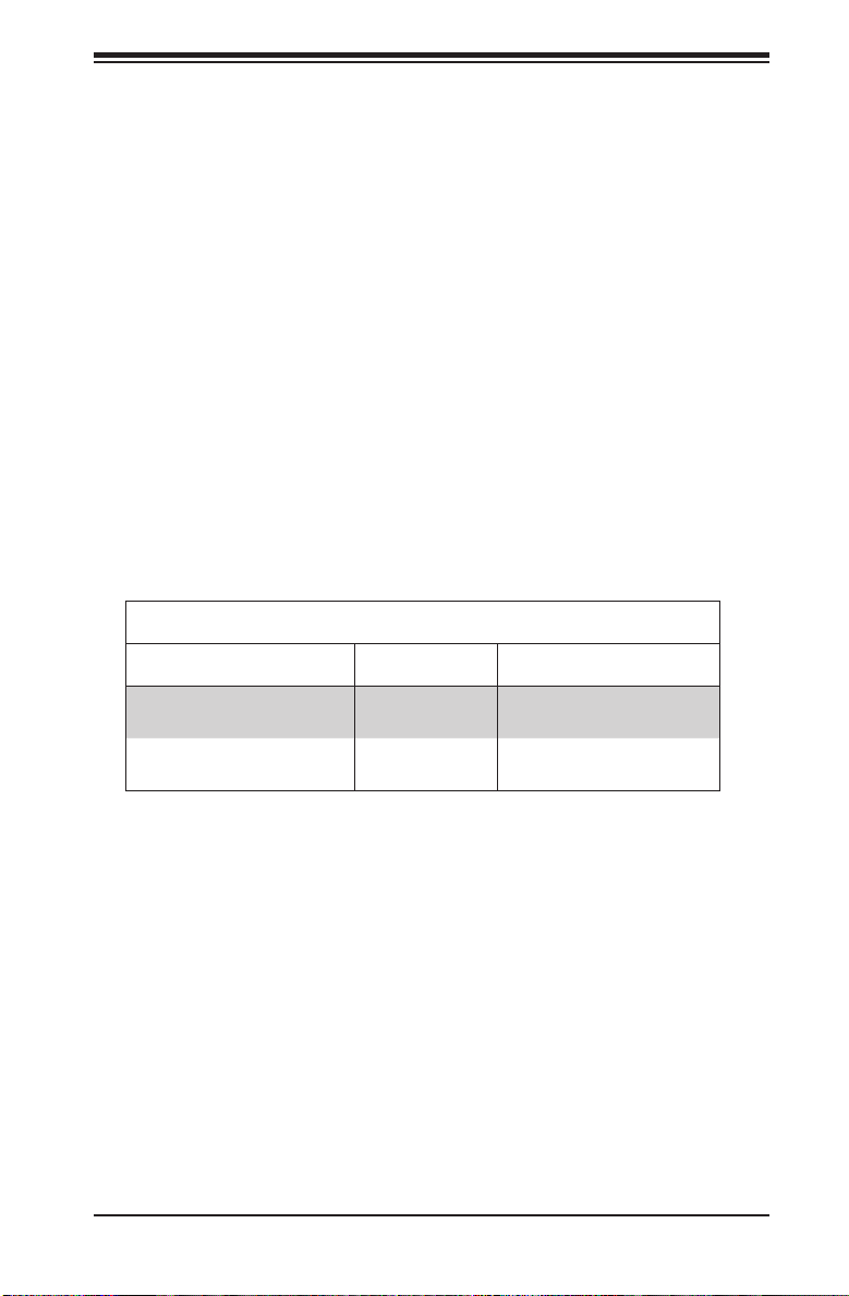
SC847 JBOD Chassis Models
Model HDD Power Supply
CSE-847E1C-R1K23JBOD 44x SAS/SATA 1200W redundant
(Titanium Level)
CSE-847E2C-R1K23JBOD 44x SAS 1200W redundant
(Titanium Level)
as compliant with UL or CSA: 847JBOD-12.
1-2 Shipping List
Refer to the Supermicro website for the latest shipping lists and part numbers for
your chassis model.
Chapter 1: Introduction
1-1

SC847 JBOD Chassis Manual
1-2
1-3 Components
The SC847 JBOD 4U high-performance chassis includes the following features:
Drives
The chassis supports forty-four hot-swap 3.5" SAS or SATA hard disk drives, 24 in
the front and 20 in the rear. The drives are supported by two backplanes.
Power Supply
The chassis features two redundant digital power supplies, each 1200 watts with a
Cooling
The chassis includes seven mid-chassis, hot-plug 80 mm heavy-duty, hot-swap
fans. System fans are powered and controlled by the BMC using 4-pin connectors.
Control Board
The JBOD control board allows the user to remotely control and monitor the chassis
reading temperature data from the backplane.
Mounting Rails
Rack mount rails allow you to mount the chassis in a rack. The rails feature snap-in
installation and quick release, and support modern square hole racks. Round hole
rack are supported with a conversion kit.
1-4 Where to get Replacement Components
If you need replacement parts for your system, to ensure the highest level
of professional service and technical support, purchase exclusively from our
Supermicro Authorized Distributors/System Integrators/Resellers. A list can be found
at: http://www.supermicro.com. Click the "Where to Buy" link.

1-3
Chapter 1 Introduction
1-5 Returning Merchandise for Service
A receipt or copy of your invoice marked with the date of purchase is required before
any warranty service will be rendered. You can obtain service by calling your vendor
for a Returned Merchandise Authorization (RMA) number. When returning to the
manufacturer, the RMA number should be prominently displayed on the outside of
the shipping carton, and mailed prepaid or hand-carried. Shipping and handling
charges will be applied for all orders that must be mailed when service is complete.
For faster service, RMA authorizations may be requested online (http://www.
supermicro.com/support/rma/).
Whenever possible, repack the chassis in the original Supermicro carton, using the
original packaging material. If these are no longer available, be sure to pack the
chassis securely, using packaging material to surround the chassis so that it does
not shift within the carton and become damaged during shipping.
This warranty only covers normal consumer use and does not cover damages
incurred in shipping or from failure due to the alteration, misuse, abuse or improper
maintenance of products.

SC847 JBOD Chassis Manual
1-4
1-6 Contacting Supermicro
Headquarters
Address: Super Micro Computer, Inc.
980 Rock Ave.
San Jose, CA 95131 U.S.A.
Tel: +1 (408) 503-8000
Fax: +1 (408) 503-8008
Email: [email protected] (General Information)
Web Site: www.supermicro.com
Europe
Address: Super Micro Computer B.V.
Het Sterrenbeeld 28, 5215 ML
's-Hertogenbosch, The Netherlands
Tel: +31 (0) 73-6400390
Fax: +31 (0) 73-6416525
Email: [email protected] (General Information)
Web Site: www.supermicro.nl
Asia-Pacic
Address: Super Micro Computer, Inc.
3F, No. 150, Jian 1st Rd.
Zhonghe Dist., New Taipei City 235
Taiwan (R.O.C)
Tel: +886-(2) 8226-3990
Fax: +886-(2) 8226-3992
Web Site: www.supermicro.com.tw
Ce manuel convient aux modèles suivants
2
Table des matières
Autres manuels Supermicro Enceinte

Supermicro
Supermicro SC216BE1C-R741JBOD Manuel utilisateur

Supermicro
Supermicro SC847E1C Series Manuel utilisateur

Supermicro
Supermicro SuperBlade 6U Manuel utilisateur

Supermicro
Supermicro SC846 JBOD Series Manuel utilisateur

Supermicro
Supermicro SC417BE1C-R1K23JBOD Manuel utilisateur

Supermicro
Supermicro SC846B JBOD Manuel utilisateur

Supermicro
Supermicro SC836B JBOD Series Manuel utilisateur

Supermicro
Supermicro CSE-826BE1C-R609JBOD Manuel utilisateur

Supermicro
Supermicro SC216B JBOD Series Manuel utilisateur

Supermicro
Supermicro SC946ED-R2KJBOD Manuel utilisateur