Subzero CL3050W/O Manuel utilisateur

SPECIFICATIONS, INSTALLATION,
AND MORE
Classic Series Wine Storage
Installation Guide

2 | Sub-Zero Customer Care 800.222.7820
Classic Series Wine Storage
Contents
3Classic Series Wine Storage
4Opening Dimensions
8Dual Installation
8Electrical
9Preparation
10 Anti-Tip Bracket
12 Placement
13 Panel Installation
15 Alignment
16 Completion
Features and specifications are subject to change at any
time without notice. Visit subzero.com/specs for the most
up-to-date information.
Important Note
To ensure this product is installed and operated as safely
and eciently as possible, take note of the following types
of highlighted information throughout this guide:
IMPORTANT NOTE highlights information that is especially
important.
CAUTION
Indicates a situation where minor injury or product
damage may occur if instructions are not followed.
WARNING
States a hazard that may cause serious injury or
death if precautions are not followed.
IMPORTANT NOTE: Throughout this guide, dimensions in
parentheses are millimeters unless otherwise specified.
IMPORTANT NOTE: Save these instructions for the local
electrical inspector.

subzero.com | 3
Product Information
Important product information, including the model and
serial number, are listed on the product rating plate. The
rating plate is located at the top frame of the unit, inside
the door. Refer to the illustration below.
If service is necessary, contact Sub-Zero Factory Certified
Service with the model and serial number. For the name of
the nearest Sub-Zero Factory Certified Service or for ques-
tions regarding the installation, visit the Product Support
section of our website, subzero.com, or call Sub-Zero
Customer Care at 800-222-7820.
Classic Series Wine Storage
RATING
PLATE
Rating plate location

4 | Sub-Zero Customer Care 800.222.7820
Opening Dimensions
STANDARD INSTALLATION
Site Preparation
If two units are installed side by side, refer to page 6.
NOTE: 3
1/2" (89) finished returns will be visible and should be finished to match cabinetry.
Shaded line represents profile of unit.
833/4"
(2127)
OPENING
HEIGHT
24" (610)
OPENING
DEPTH
FRONT VIEW
SIDE VIE
W
TOP VIEW
W
OPENING WIDTH
3/4" (19)
TYPICAL
FRAMED
CABINETRY
W
FILLER
31/2" (89)
FINISHED
RETURN
FRAMELESS
CABINETRY
W
3/4" (19)
TYPICAL
31/2" (89)
FINISHED
RETURN
OPENING WIDTH W
Model CL3050W 29⁄" (749)
subzero.com | 5
Opening Dimensions
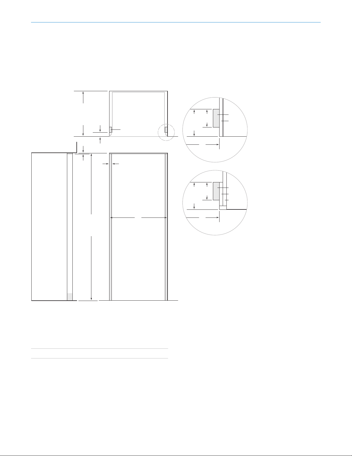
FLUSH INSET INSTALLATION
Dimensions assume a ⁄" (19) panel thickness. If two units
are installed side by side, refer to page 7.
FLUSH INSET WIDTH W
Model CL3050W 32" (813)
84"
(2134)
FLUSH
INSET
HEIGHT
1/4"
(6)
263/16"
(665)
FLUSH
INSET
DEPTH
23/16"
(56)
FRONT VIEW
SIDE VIE
W
TOP VIEW
11/4"
(32)
W
FLUSH INSET WIDTH
FINISHED
CLEATS
NOTE: 31/2" (89) finished returns and shaded areas will be visible and should be finished to match cabinetry.
Shaded line represents profile of unit with 3/4" (19) panel.
511/16"
(145)
FINISHED
RETURN
FILLER
FRAMED
CABINETRY
W
CLEAT
3/4" (19)
TYPICAL
31/2"
(89)
511/16"
(145)
FINISHED
RETURN
FRAMELESS
CABINETRY
W
31/2"
(89)
CLEAT
3/4" (19)
TYPICAL
Site Preparation

6 | Sub-Zero Customer Care 800.222.7820
Opening Dimensions
DUAL STANDARD INSTALLATION
NOTE: 3
1/2" (89) finished returns will be visible and should be finished to match cabinetry.
Shaded line represents profile of unit.
833/4"
(2127)
OPENING
HEIGHT
24" (610)
OPENING
DEPTH
FRONT VIEW
SIDE VIE
W
TOP VIEW
W
OPENING WIDTH
3/4" (19)
TYPICAL
FRAMED
CABINETRY
W
FILLER
31/2" (89)
FINISHED
RETURN
FRAMELESS
CABINETRY
W
3/4" (19)
TYPICAL
31/2" (89)
FINISHED
RETURN
DUAL OPENING WIDTH W
Two Models CL3050W 59⁄" (1518)
Model CL3050W and 30" Classic Series Model 59⁄" (1518)
Model CL3050W and 36" Classic Series Model 65⁄" (1670)
A dual installation kit is required for this installation.
Site Preparation

subzero.com | 7
Opening Dimensions
DUAL FLUSH INSET INSTALLATION
84"
(2134)
FLUSH
INSET
HEIGHT
1/4"
(6)
263/16"
(665)
FLUSH
INSET
DEPTH
23/16"
(56)
FRONT VIEW
SIDE VIE
W
TOP VIEW
FINISHED
CLEATS
11/4"
(32)
W
FLUSH INSET WIDTH
NOTE: 3
1/2" (89) finished returns and shaded areas will be visible and should be finished to match cabinetry.
Shaded line represents profile of unit wit
h 3/4" (19) panel.
511/16"
(145)
FINISHED
RETURN
FILLER
FRAMED
CABINETRY
W
CLEAT
3/4" (19)
TYPICAL
31/2"
(89)
511/16"
(145)
FINISHED
RETURN
FRAMELESS
CABINETRY
W
31/2"
(89)
CLEAT
3/4" (19)
TYPICAL
DUAL FLUSH INSET WIDTH W
Two Models CL3050W 62⁄" (1581)
Model CL3050W and 30" Classic Series Model 62⁄" (1581)
Model CL3050W and 36" Classic Series Model 68⁄" (1734)
Dimensions assume a ⁄" (19) panel thickness. A dual instal-
lation kit is required for this installation.
Site Preparation

8 | Sub-Zero Customer Care 800.222.7820
Dual Installation
If two units are installed side by side, a dual installation kit
may be required. Installations without a custom filler strip
require a dual installation kit. If a dual installation kit is not
specified, a 2" (51) filler strip is recommended between
units. Dual installations without a filler strip can only be
accomplished using two units with opposite hinges. Refer
to the illustrations below.
Dual installation kits are available through an authorized
Sub-Zero dealer. For local dealer information, visit the
find a showroom section of our website, subzero.com.
For questions regarding the installation, call Sub-Zero
Customer Care at 800-222-7820.
Electrical Requirements
Installation must comply with all applicable electrical codes.
The electrical supply should be located within the shaded
area shown in the illustration below. A separate circuit ser-
vicing only this appliance is required. A ground fault circuit
interrupter (GFCI) is not recommended and may cause
interruption of operation.
ELECTRICAL REQUIREMENTS
Electrical Supply 115 VAC, 60 Hz
Service 15 amp dedicated circuit
Receptacle 3-prong grounding-type
CAUTION
The outlet must be checked by a qualified electrician
to be sure it is wired with the correct polarity. Verify
the outlet is properly grounded.
WARNING
If the supply cord is damaged, it must be replaced by
the manufacturer, its service agent or similarly quali-
fied persons in order to avoid a hazard.
WARNING
Do not use an extension cord, two-prong adapter, or
remove the power cord ground prong.
751/2" (1918)
FROM FLOOR
7"
(178) E
6"
(152)
RIGHT SIDE
OF OPENING
Electrical supply location
Site Preparation
WITHOUT FILLER STRIP FILLER STRIP
Opposite hinges
Same side hinges

subzero.com | 9
Preparation
Uncrate the unit and inspect for damage. Remove the
wood base and discard the shipping bolts and brackets.
Remove and recycle packing materials. Do not discard the
kickplate, anti-tip brackets, and hardware.
Completely retract the front leveling legs to allow the unit
to be moved into position. The front and rear leveling legs
can be adjusted from the front once the unit is in position.
Remove the drain pan from the base of the unit to avoid
damage and to allow for proper placement of the appli-
ance dolly.
The grille assembly should be removed prior to moving the
unit. To remove, pull out on the bottom edge of the grille
and rotate upward. Loosen the back two grille mounting
screws and remove the front two grille mounting screws.
Refer to the illustrations below. With the grille held firmly,
pull forward to remove.
Site Preparation
Grille removal
Grille mounting screws
BACK GRILLE
SCREW
FRONT
GRILLE SCREW

10 | Sub-Zero Customer Care 800.222.7820
WOOD FLOOR APPLICATION
After properly locating the anti-tip brackets in the open-
ing, drill pilot holes ⁄" (5) diameter maximum in the wall
studs or wall plate. Use the #12 screws and washers to
secure the brackets. Verify the screws penetrate through
the flooring material and into the wall studs or wall plate a
minimum of ⁄" (19). Refer to the illustration below.
CONCRETE FLOOR APPLICATION
After properly locating the anti-tip brackets in the opening,
drill pilot holes ⁄" (5) diameter maximum in the wall studs
or wall plate. Drill ⁄" (10) diameter holes into the concrete
a minimum of 1⁄" (38) deep. Use the #12 screws and
washers to secure the brackets to the wall, and use the ⁄"
wedge anchors to secure the brackets to the floor. Verify
the screws penetrate the wall studs or wall plate a mini-
mum of ⁄" (19). Refer to the illustration below.
Anti-Tip Bracket
WARNING
To prevent the unit from tipping forward, the anti-tip
brackets must be installed.
The two anti-tip brackets must be installed exactly 24"
(610) from the front of the opening to the back of the
brackets and a minimum of 4" (102) from the sides of the
opening. This depth will increase to 26⁄" (665) for a flush
inset installation based on ⁄" (19) thick panels. Failure to
properly position the anti-tip brackets will prevent proper
engagement.
Use all anti-tip bracket hardware as instructed for wood or
concrete floors.
IMPORTANT NOTE: For wood or concrete floor applica-
tions, if the #12 screws do not hit a wall stud or wall plate,
use the #8 screws and #12 washers with the wall anchors.
IMPORTANT NOTE: In some installations the subflooring
or finished floor may necessitate angling the screws used
to fasten the anti-tip brackets to the back wall.
ANTI-TIP HARDWARE
2Anti-tip brackets
12 #12 x 2⁄" pan head screws
4⁄"–16 x 3⁄" wedge anchors
12 #12 flat washers
4#8–18 x 1⁄" truss head screws
4Nylon Zip-it® wall anchors
Site Preparation
4" (102)
MIN
24"
(610)
SUBFLOORING
WOOD FLOOR
WALL PLATE
FINISHED
FLOORING
4" (102)
MIN
24"
(610)
SUBFLOORING
CONCRETE
FLOOR
WALL PLATE
FINISHED
FLOORING
11/2"(38)
min
SUBFLOORING
CONCRETE
FLOOR
WALL PLATE
FINISHED
FLOORING
11/2"(38)
MIN
Wood floor
Concrete floor
Ce manuel convient aux modèles suivants
10
Table des matières
Langues :
Autres manuels Subzero Refroidisseur de vin

Subzero
Subzero 400-2 SERIES Manuel utilisateur

Subzero
Subzero UW-24 Manuel utilisateur

Subzero
Subzero 424 Manuel utilisateur

Subzero
Subzero WOLF UW Series Manuel utilisateur

Subzero
Subzero WOLF ICB WS Series Manuel utilisateur

Subzero
Subzero WS-30 Manuel utilisateur

Subzero
Subzero Classic Series Manuel utilisateur

Subzero
Subzero 400-2 SERIES Manuel utilisateur


