3
2-INSTALLATION AND OPERATION:
2.1 Unpacking
Open the transportation packing carefully and check for any apparent damage.
Prior to leaving the plant all Studio R amplifiers are fully tested and inspected and
ought to reach you in perfect conditions. Should any damage be found on them,
please notify the carrier immediately. Only a forwarding agent may request the
carrier to take actions concerning the damage occurred during the
transportation. Make sure to keep all packing for inspection. It might be a good
idea to keep the packing even when your amplifier has come in perfect conditions.
Whenever it has to be transported, use the original packing or rack standard
CASE, with frontal bars.
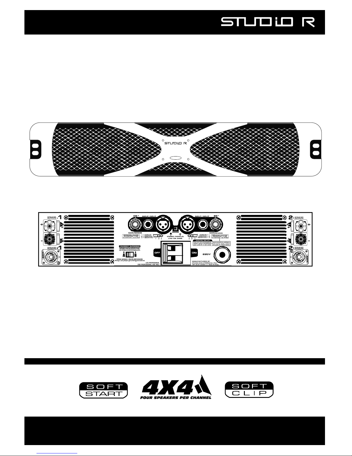
2.2 Assembling
Your amplifier is designed to be assembled on a standard 19” CASE, with 02
units/rack. For a movable use, in addition to 4 holes for assembly on the front
panel, also use the four holes located on the amplifier rear “grips”. The ventilation
on the apparatus rear portion and the front air outlet are essential for its proper
performance. This system provides enough cooling for all load rates, assuming
that the rack rear portion is open and unblocked. On racks with a closed rear
portion, it is vital to install additional fans on same in such a way to pressurize
them, ensuring a good air source for your amplifier internal fan.
2.3 Operating precautions.
Make sure the power line AC voltage is the appropriate for powering your X
Series amplifier. The warranty does not cover damages resulting from using the
device on the wrong voltage.
Prior to making any connection, both regarding input and output, make sure that
the power switch is off. Even though the amplifier is fitted with overload
protection as well as a Soft Start (silent activation), it is recommendable to
always keep the gain controls low when turning it on. This operation will prevent
any possible damages to the speakers should there be an excess signal on the
inputs. Seek to acquire cables, connectors, and speaker of good quality and
appropriate capacity. Check the wiring capacity table (Section 2.5) to determine
the appropriate measures for different impedances and lengths of cables.
Most of the systems intermittences and faults
occur due to defective wires and connectors.
Use quality connectors, wires, and welding technique to ensure seamless
operations.