B. MAIN FEATURES
Voltage:AC 120V~60Hzor 230V~50/60 Hz
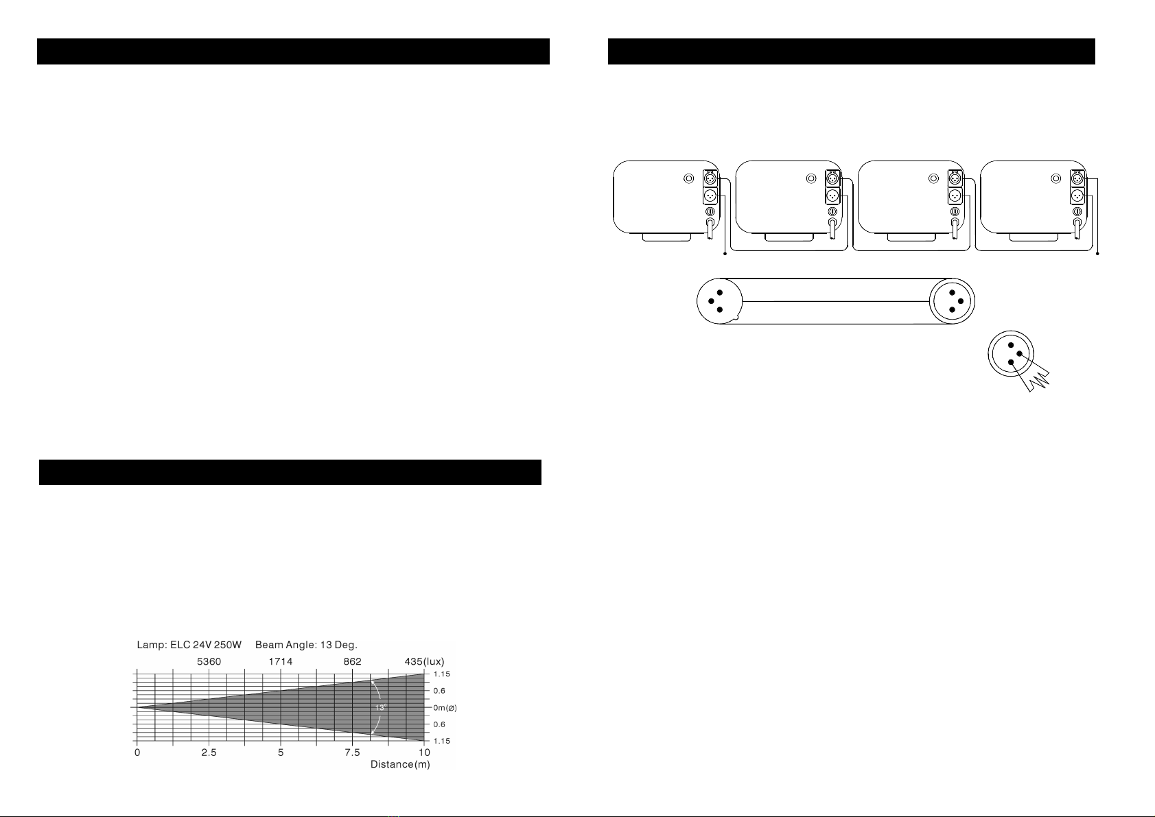
Bulb:ELC3 24V 250W
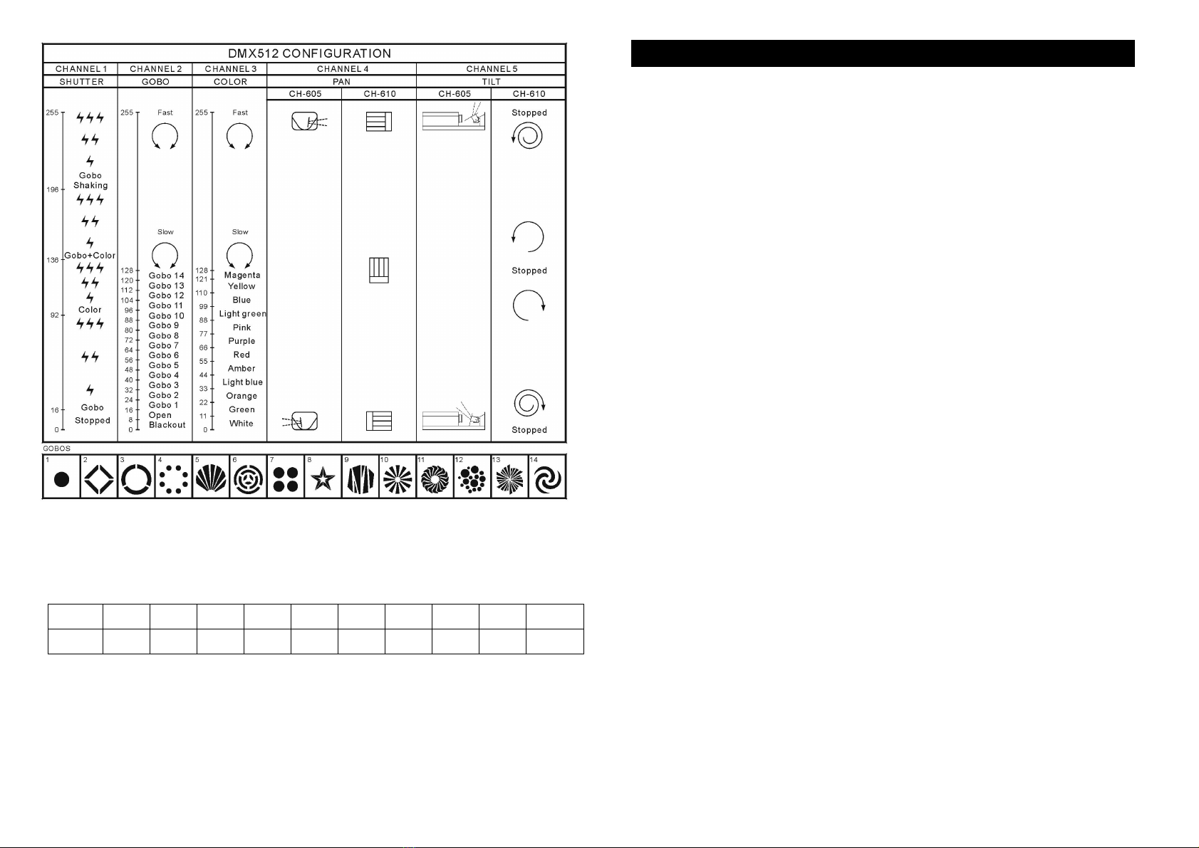
The unit is aDMX512 scanner. It features full DMX512 control, 14 gobos plus
open and 11 colors plus white, accurate focusable optics systemand stepper
motor with blackout feature. Fan cooled.
It can be operated byDMX512 control or can be used as an individual unit without
a control.
It can be linked together in master/slave combination units, as manyas required in
4channels and run bybuilt-in preprogrammed chase sequences automaticallyor
bysound activation through an internal microphone to create an intelligent effect.
Please use a 3 pin XLR cable/plug when connecting themtogether.
It features different preprogrammed chase patterns.
Dimensions:500mm x 200mm x 155 mm / 19.69 in x 7.87 in x 6.1 in
Weight:10 kg / 22 lbs
C. LAMP
ELC3 24V 250W (300 Hrs)
Alwaysswitch off the mains supplyand never handle the lampor luminaire when
it is hot.
Do not touch the bulb with bare hands. Ifthis does happen, clean the lampwith
denatured alcohol and wipe with a lint free cloth before installing.
D. HOW TO CONTROL THE UNIT
(1) By universal DMX controller
The DMX512 is widelyused in intelligent lighting control, with amaximumof512
channels.
120 ohm 1/4W
Termination reduces signal errors and to avoid signal
(Resistance 120 ohm 1/4W) between pin2 (DMX-) and
transmission problems and interference. It is always
3
pin3 (DMX+) of the lastfixture.
advisable to connect a DMX terminal.
2
DMX -
1
COMMON
DMX +
3
1
DMX512
2
1234
DMX INPUTDMX OUTPUT
2
3
1
Ÿ ADMX512 systemrequires acontroller, lighting equipment and cable. These are
connected together in a “daisychain”with the terminator at the end. The cable
cannot be branched or split to a “Y”cable.
Ÿ The terminator requires a90-120 Ohm1/4 Watt resistor soldered between two
signal cables.
Ÿ The DMX512 uses a veryhigh-speed signal. Inadequate or damaged cables, bad
solder joints or corroded connectors can easilydistort the signal and shut down
the system. A reliable DMX512 systemstarts with good qualitycables.
Ÿ Each lighting unit needs to have an address set to receive the data sent bythe
controller. The address number is between 0-511. The end ofthe DMX512
systemshould be terminated reducing signal errors.
Ÿ 3 pin XLR connectors are more popular than 5 pin XLR.
3 pin XLR: Pin 1: GND, Pin 2: Negative signal (-), Pin 3: Positive signal (+)
5 pin XLR: Pin 1: GND, Pin 2: Negative signal (-), Pin 3: Positive signal (+)