Stab ROTOR SAT HH100 Manuel utilisateur

CONTENTS
- INTRODUCTION ......................................................................................................... page 1
- ROTOR TECHNICAL DATA ..................................................................................... page 2
- MOUNTING INSTRUCTIONS .................................................................................. page 3
1. Where to install the sat dish .................................................................................... page 3
2. Rotor’s installation.................................................................................................... page 3
3. Connections ................................................................................................................ page 4
3.1 Specifications of the recommended coaxial cable........................................... page 4
3.2 Map to determine the installation parameters - EUROPE MAP ................ page 5
NORTH AFRICA MAP ..................................................................................... page 5a
MIDDLE EAST MAP......................................................................................... page 5b
SOUTH EAST ASIA MAP ................................................................................ page 5c
4. How to find out the elevation angle of the Rotor ................................................. page 6
5. How to find out the elevation value of the dish .................................................... page 6
6. Dish pointing .............................................................................................................. page 6
10. EAST - WEST limits (only for enabled receivers)............................................. page 9
11. Recalculation function ............................................................................................ page 9
12. Return to the 0° position of the rotor (only for enabled receivers)................. page 10
13. Autofocus (only for enabled receivers) ................................................................ page 10
- PROBLEMS SOLVING GUIDE ................................................................................. page 11
- WARRANTY CONDITIONS ...................................................................................... page 12
- HOW TO CONTACT US ............................................................................................. page 13

Via Seminiato, 79
44031 AMBROGIO (FE) ITALY
http:// www.stab-italia.com
e-mail: [email protected]
ROTOR SAT HH100 - HH120
Rotor Sat HH100-HH120 instructions manual – page 1
Attention:
•To connect the motor without interface it is necessary that your receiver includes DiSEqCTM 1.2 protocol.
•Please read carefully this instructions manual before installing and using it.
•For the movement and memorization commands, see the receiver’s instructions manual.
DEAR CUSTOMER,
Congratulations! You are now the owner of STAB ROTOR SAT.
This is the first sat motor developed by STAB in cooperation with EUTELSAT in order to define the
DiSEqCTM 1.2 standard.
The DiSEqCTM 1.2 system is a trademark of EUTELSAT.
All drawings and technical data are STABTM property and can be changed without prior notice.

Rotor Sat HH100-HH120 instructions manual – page 2
ROTOR TECHNICAL DATA
ROTOR SAT HH100 ROTOR SAT HH120
OPTIONAL
SPECIFICATIONS
- Operating protocol DiSEqCTM 1.2 Level
- Maximum antenna diameter 100 cm
- Maximum antenna weight 12 Kg
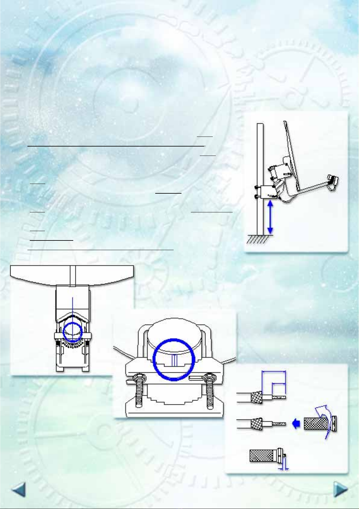
- Antenna support length 125mm
- Rotation angle ±62°
- Rotation speed 1,8°/s(18V) 1,2/s(13V)
- Operating power supply 13 / 18 Vdc
- Consumption in stand-by mode 30mA
- Consumption in operating mode 190mA
- Starting consumption max 350mA
- Operating temperature -40°C +80°C
- Maximum relative humidity 100%
-Programmablepositions 49 satellites
- Preset positions 26 satellites
- Connectors F type
- Connections Sat coaxial cable
- Mechanical limits ±70°
- Software programmable limits from 5° to 62°
- Fine tuning impulse0,1°
- Inclination max 70°
- Weight 3 Kg
OPTION
- Extension for antenna support
SPECIFICATIONS
- Operating protocol DiSEqCTM 1.2 Level
- Maximum antenna diameter 120 cm
- Maximum antenna weight 17 Kg
- Antenna support length 180mm
- Rotation angle ±62°
- Rotation speed 1,1°/s(18V) 0,8/s(13V)
- Operating power supply 13 / 18 Vdc
- Consumption in stand-by mode 30mA
- Consumption in operating mode 190mA
- Starting consumption max 350mA
- Operating temperature -40°C +80°C
- Maximum relative humidity 100%
-Programmablepositions 49 satellites
- Preset positions 26 satellites
- Connectors F type
- Connections Sat coaxial cable
- Mechanical limits ±70°
- Software programmable limits from 5° to 62°
- Fine tuning impulse0,1°
- Inclination max 70°
- Weight 3,2 Kg

MOUNTING INSTRUCTIONS
Rotor Sat HH100-HH120 instructions manual – page 3
1. Where to install the sat dish
1.1 Choose a position from where the dish can see the SOUTH without any impediments or obstructions.
Buildings, trees, water-pipes etc. can block partially or completely the sat reception.
2. Rotor’s installation
2.1Fix the supporting pole (ø 50 ÷ 83 mm diameter) in a perfectly FIG. 1
vertical position.
2.2 Use the provided support to fix the rotor to the pole (fig. 1).
It is strictly forbidden to install the motor upside-down.
2.3 Point the rotor position to the south using a compass (fig. 2).
2.4 Assemble the dish according to the manufacturer’s instructions.
2.5 Fixthedishtotherotor’s antenna supportwiththeprovidedbrackets
(fig. 1).
2.6 Align the dish to rotor’s pole indicator (fig. 2 - 3).
2.7 On a coax cable approximately 1,5 m long, set up two F-connectors
(fig. 4) and connect the LNB to the rotor’s LNB plug (fig. 5 - cable 1).
2.8 Fit an F-connector on each end of the cable going to the receiver
(fig. 4) and connect the rotor’s REC plug to the plug of yourreceiver
(fig. 5 - cable2).
Warning: - See cable specifications on page 4.
MINIMUM
HEIGHT
TO AVOID
VIBRATION
F-CONNECTOR
3 mm
15 mm
8 mm
FIG. 2
FIG. 3
FIG. 4
SOUTH

3. Connections (fig. 5)
Rotor Sat HH100-HH120 instructions manual – page 4
cable n. 1
cable n. 2
TV
LNB
RECEIVER
ANT. 2
ANT. 1 REC LNB
3.1 Specifications of the recommended coaxial cable
CABLE
LENGTH TO 30 M
(to 98.4 feet) FROM 30 TO 60 M
(from 98.4 to 196.8 feet)
Cable type sat coaxial cable sat coaxial cable
Inner conductor CU ø=1,02 mm CU ø=1,13 mm
Inner conductor resistance 22 ohm/Km 18 ohm/Km
Outside conductor resistance 22 ohm/Km 10 ohm/Km
A bad quality cable can prejudice the motor correct working!
Please follow the next specifications:
cable n. 2
cable n. 1
(provided)
FIG. 5 RECEIVER ROTOR LNB
Ce manuel convient aux modèles suivants
1
Table des matières
Autres manuels Stab Moteur


