SRC RANGER 4000 S Manuel de programmation
RangerSInstallationandtroubleshooting
1
RANGER 4000 S
SRC IRRIGATION CONTROLLERS
INSTALLATION&TROUBLESHOOTINGMANUAL

RangerSInstallationandtroubleshooting
2
CopyrightOctober2018.Allrightsreserved.Nopartofthispublicationmay
bereproduced,storedinaretrievalsystem,ortransmittedinanyformor
byanymeanselectronic,mechanical,photocopying,recordingor
otherwisewithoutthepriorpermissionofthepublisher.
450-230-0023/B

RangerSInstallationandtroubleshooting
1
Chapter1:IntroducingRKS+ ....................................................................................................3
TheController .......................................................................................... 3
IrrigationFeatures .................................................................................... 3
Chapter2:SystemInstallation .................................................................................................5
MountingtheController ................................................................................. 5
ConnectingtheController............................................................................... 6
GroundingtheController ......................................................................... 6
ConnectingSensors......................................................................................... 7
ConnectinganETDevice ................................................................................. 7
UsingaConnectedDevice(WeatherStation) .................................................. 8
ConfiguringETInput................................................................................. 9
CheckingtheCurrentAggregatedETandRain .............................................. 15
ReadingcurrentaggregatedETandRainfigures..................................... 15
ConnectingaRainSensor.............................................................................. 17
ConfiguringforaRainSensor ................................................................. 19
SettingHourlyMaximumRainandRainAlarmLevel..................................... 23
SettingtheHourlyMax.RainandRainAlarmLevel ................................ 24
ConnectingaFlowSensor ............................................................................. 26
EnablingFlowSensorInput(pulses).............................................................. 27
EnablingflowsensorpulseinputintheRKS+ ......................................... 27
ConfiguringforFlowSensorInput................................................................. 29
SelectingSensorType............................................................................. 29
Usingabuilt‐incalibrationprofile .......................................................... 29
SettingtheFlowSensorAdjustment....................................................... 32
Adjustingtheflowsensorinput.............................................................. 32
ViewingtheCurrentFlow ............................................................................. 33
ConnectinganAlarm..................................................................................... 35
ConnectingaMoisturesensor ...................................................................... 36
Connecting,ConfiguringandUsingMoistureSensors ................................... 36

RangerSInstallationandtroubleshooting
2
Connectingandconfiguringamoisturesensor....................................... 37
AssigninganIDtoasoilmoisturesensor ............................................... 37
Configuringasoilmoisturesensor ......................................................... 39
Chapter3:Systemactivation .................................................................................................43
Stationlicense ........................................................................................ 43
Moisturelicense ..................................................................................... 45
Chapter4:TroubleshootingfromtheController...................................................................47
TestingStations ............................................................................................. 47
Enablingcurrentreadings....................................................................... 47
Runningthe"ElectricalTest" .................................................................. 49
Specialcurrentreadingsfromthestationtest..................................51
Runningthe"WaterTest".............................................................................. 51
Runningthetestprogram....................................................................... 51
TestingPrograms........................................................................................... 53

RangerSInstallationandtroubleshooting
3
Chapter1:IntroducingRanger4000S
TheRanger4000Sisamicroprocessorbasedirrigationcontrolsystem.A
centralcontrollerandupto100fieldstationscompriseacompletesystem.
Inadditionthecontrollerwillacceptinputfromseveralexternalsensorsin
ordertoadjustitsirrigationtothelocalweatherconditions.
TheController
TheheartofaRanger4000Sbasedsystemisthecontroller.Thisisa
microprocessorcontrolleddevicethatstoresyourirrigationprogramsand
Ranger4000Sindividualstationsinthefieldwhentoactivatetheir
valve(s).
IrrigationFeatures
HerearethemainfeaturesthattheRanger4000Sutilizestohelpyou
automateyourirrigation:
• Controlsupto100solenoidsattachedtovalvesorrelaysviathe
built‐inconnectionboardandthreeexpansionboards.
• ProvidesETcorrectedirrigationforoptimaladjustedwater
consumption.
• Measureswaterflowandraisesalarmsorhaltsirrigationon
unexpectedflow.
• Allowsfor10independentirrigationprograms.Inadditionthereis
afixedtestprogramthatactivatesall100stationsinturn.
• Aprogramcanactivateupto100stationsinnamedorder.
• Eachstationcanrunforupto17:59:50(Infact,youcanboostthis
evenfurtherbyincreasingthe"waterbudget".
• Eachprogramcanactivateaoneormoreboosterpumpsinaddition
tothestations.
• Mastervalvesandboosterpumpswillbeactivatedinparallelinall

RangerSInstallationandtroubleshooting
4
connectionandexpansionboards.
• Allprogramshave12starttimesperday.
• Allprogramscanrunsimultaneously(tocapacityofthetransformer
ancconnectionboard).
• Youconfigureeachprogramtorunonanyselectionofdaysina14
dayperiod,oronodd/evendates.
• Youcanactivateoneormorevalvesorprogramsmanuallywhile
oneormoreprogramsarerunning,uptoatotalof12
simultaneouslyrunningvalves.
• Amastervalvecanbeselectedthatwillopenwhenanyprogramor
stationisrun.Youtypicallyassignmastervalvestatustothevalve
controllingaccesstomunicipalwaterorpumpingstation.
• Upto10moisturesensorsthatcanmonitorsoilmoistureandadjust
irrigationaccordingly.

RangerSInstallationandtroubleshooting
5
Chapter2:SystemInstallation
MountingtheController
ThoughtheRanger4000Sisdesignedtoresistbothrainanddirectsun
light,youshouldplaceitinafriendlierenvironmentifpossible.Installing
theRanger4000Sinsideautilityroomorashedistheperfectsolution,but
ifthisisnotpossible,trytoplaceitsomewheredryandoutofsight.
Furthermore,makesurethatyouplacethecontrollerinalocationthat
meetstheserequirements:
• Thecontrollermusthaveaccessto230VAC.
• Youmustbeabletoconnectallcablestothecontrolleratthe
location.
Tominimizeelectromagneticinterference,makesurethatthecontrolleris
placedatleast4,5mawayfromanyhigh‐drawmotorslikeairconditioners,
refrigerators,poolpumpsetc.
3 Useapentoputmarksonthewallthroughtheholeinthebackof
thecontrollercabinet.
4 Ifyou'replacingthecontrolleronaconcretewall,takedownthe
controller,drilloutthehole,putinthewallanchor,andputbackthe
controlleronthewall.
5 Fastenthescrewinthewallthroughtheholesinthebackofthe
controllercabinet.
Nowthecontrollershouldbemountedfirmlyonthewall.Aftermounting
thecontroller,it'stimetoconnectthepowerandconnectboards‐follow
theinstructionsinthenextsectiontodothis.

RangerSInstallationandtroubleshooting
6
ConnectingtheController
GroundingtheController
TosecureyourRanger4000Sagainstlightning,youmustensurethatthe
controllerisgroundedthroughagroundrodconnectedtothegroundlugs.
Warning
YouwillvoidthewarrantybynotgroundingyourRanger4000
Sproperly.
RangerSInstallationandtroubleshooting
7
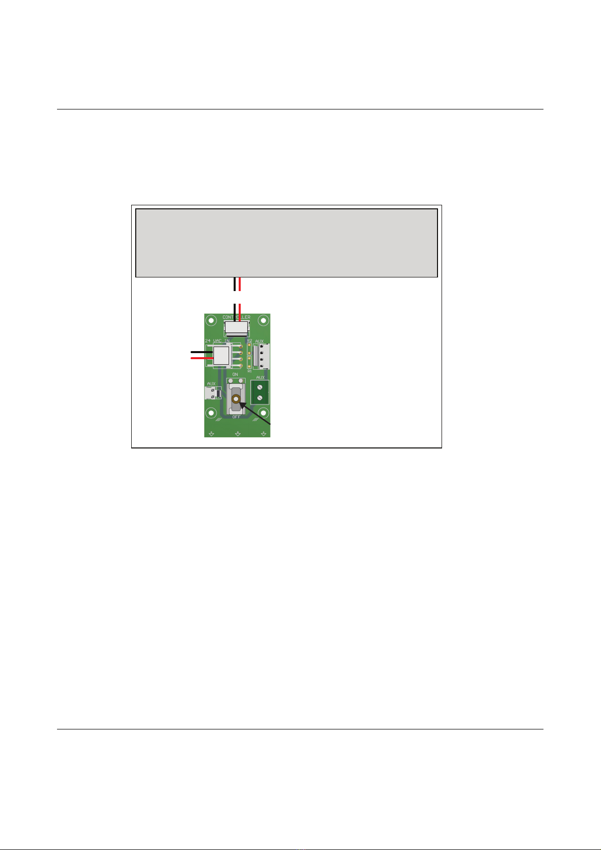
Thepowerdistributor
Thepowerdistributordelivers24VACtothecontrollerandtovariousAUX
connections.Italsohasapowerswitch.
24VAC in 24VAC out
24VAC out
Power switch
24VAC to controller
Controller
RangerSInstallationandtroubleshooting
8
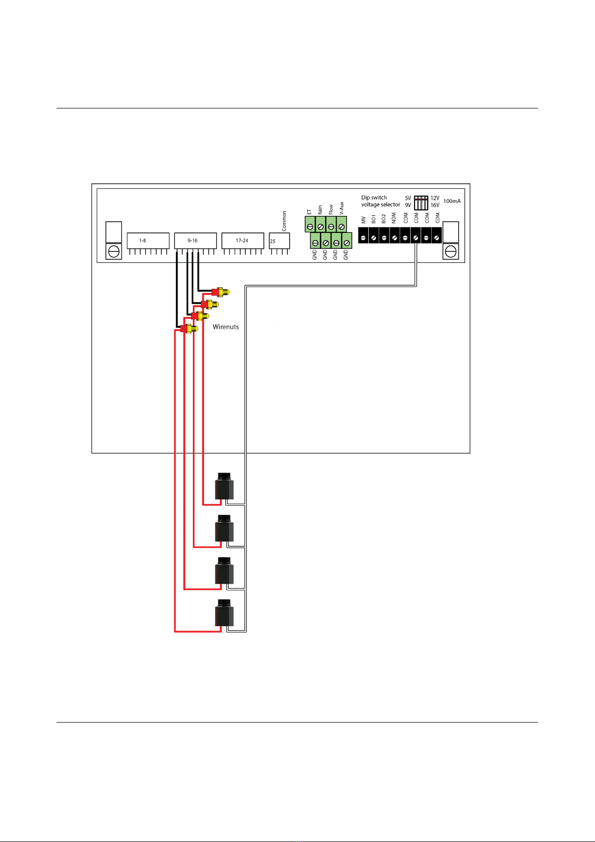
Connectingtheconventionalfieldwires
ConnectingSensors
TheRanger4000Stakesinputfromdifferentsensortypes:ETdevices,rain
sensors,flowsensorsandregularauxiliaryalarms.Thissectionsshowsyou
howtoconnectthesesensorstothecontroller.
ConnectinganETDevice
TheRanger4000SsupportsETintwoways:
1."ETEnabled"modeinwhichthecontrollerjustletsanexternaldevice
tellitwhentoirrigateandwhentostaypassive.Inthismodethecontroller
supportstwoETdevices:WR‐7andWR100i.Tomakethecontrollerreceive
instructionsfromanETdevice,connectthe"ETenableA"fromthedevice
tothegreenterminalslabeled"ET."
2."ETPulses"modewhereyouconnectaweatherstationthat
continuouslytellsthecontrollerhowmuchwaterisevaporating.
Combinedwiththeinputfromarainsensorthecontrollerwillthenonits
ownfigureouthowmuchtoirrigate.Runninginthismodeyoustilljust
connecttheweatherstationtotheETterminals.
Table des matières


