Spatz Sniffer Manuel utilisateur

SNIFFER
3D Mini HDMI Analyzer
O
O
Op
p
pe
e
er
r
ra
a
at
t
ti
i
io
o
on
n
nM
M
Ma
a
an
n
nu
u
ua
a
al
l
l

DISCLAIMERS
The information in this manual has been carefully checked and
is believed to be accurate. SPATZ assumes no responsibility for any
infringements of patents or other rights of third parties which may
result from its use.
SPATZ assumes no responsibility for any inaccuracies that may be
contained in this document. SPATZ also makes no
commitment to update or to keep current the information contained
in this document.
SPATZ reserves the right to make improvements to this document
and/or product at any time and without notice.
COPYRIGHT NOTICE
No part of this document may be reproduced, transmitted,
transcribed, stored in a retrieval system, or any of its part translated
into any language or computer
file,
in any form or by any means—
electronic, mechanical, magnetic, optical, chemical, manual, or
otherwise—without express written permission and consent from
SPATZ.
© Copyright 2011 by SPATZ. All Rights reserved.
Version 1.1 August 2011
TRADEMARK ACKNOWLEDGMENTS
All products or service names mentioned in this document may be
trademarks of the companies with which they are associated.

SAFETY PRECAUTIONS
Please read all instructions before attempting to unpack, install or
operate this equipment and before connecting the power supply.
Please keep the following in mind as you unpack and install this
equipment:
•Always follow basic safety precautions to reduce the risk of
fire,
electrical shock and injury to persons.
•To prevent
fire
or shock hazard, do not expose the unit to rain,
moisture or install this product near water.
•Never spill liquid of any kind on or into this product.
•Never push an object of any kind into this product through any
openings or empty slots in the unit, as you may damage parts
inside the unit.
•Do not attach the power supply cabling to building surfaces.
•Use only the supplied power supply unit (PSU). Do not use the PSU
if it is damaged.
•Do not allow anything to rest on the power cabling or allow any
weight to be placed upon it or any person walk on it.
•To protect the unit from overheating, do not block any vents or
openings in the unit housing that provide ventilation and allow for
sufficient
space for air to circulate around the unit.
REVISION HISTORY
VERSION NO.
DATE DD/MM/YY
SUMMARY OF CHANGE
VS1
09/02/12
First Release


CONTENTS
1. Introduction............................................ 1
2. Applications........................................... 1
3. Package Contents ................................ 1
4. System Requirements............................ 1
5. Features .................................................. 2
6. Operation Controls and Functions....... 3
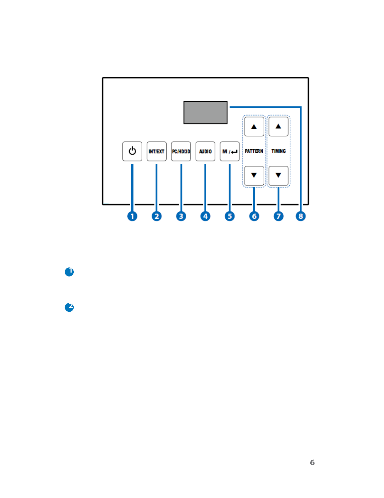
6.1 Front Panel ........................................3
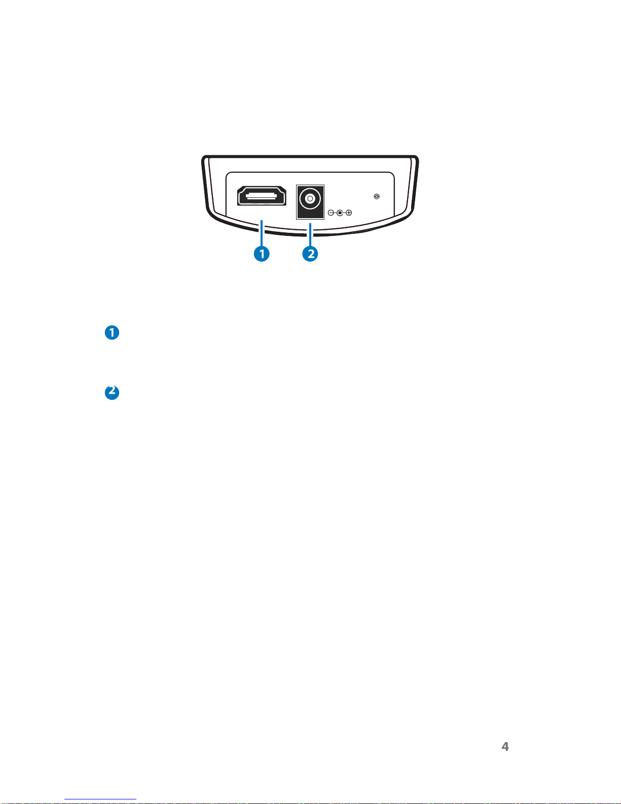
6.2 Rear Panel.........................................4
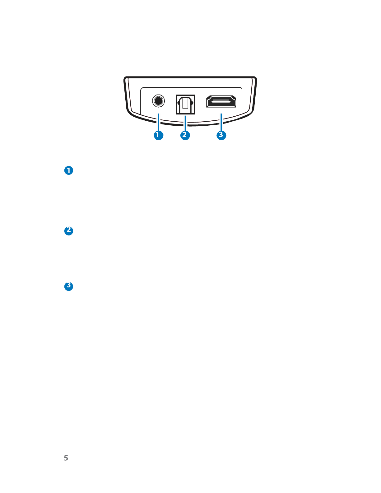
6.3 Top Panel ..........................................5
7 OSD Menu ............................................... 7
7.1 System Info ........................................8
7.2 Sink Edid ............................................9
7.3 Source Infoframe .............................9
7.4 CEC Command ...............................9
7.5 Audio Return.....................................9
7.6 Deep Color Set...............................10
7.7 Exit....................................................10
8. OLED Display ........................................ 11
9. Timing Table (Pattern Mode) .............. 12
10. Support Pattern Table........................ 13
11. Connection Diagram ........................ 15
12. Specifications .................................... 16
13. Acronyms ........................................... 17

1. INTRODUCTION
The 3D Mini-HDMI Analyzer is a tool for checking both source (Blu-
ray or DVD players) and display devices (TV or monitors). With touch
button controls and built-in OLED (Organic Light Emitting Diode)
display it can show the status and information of both the input and
output devices connected to it through HDMI.
The analyzer can be used to analyze the input source device info-
frame and output sink device EDID. It also has a built-in pattern
generator that can be used to test the capabilities of the output
device including 3D and resolution/timing support.
2. APPLICATIONS
• Apparatus testing
• Equipment checking
• EDID checking
• HDCP or 3D support
verification
• Production testing
• R&D design and debug
3. PACKAGE CONTENTS
• 3D Mini-HDMI Analyzer
• Operation Manual
• 5 V Power Adaptor
4. SYSTEM REQUIREMENTS
HDMI input port connected to the source/HDMI system with HDMI
cable and HDMI output connected to the display/HDMI system with
HDMI and/or
amplifier.

5. FEATURES
• Supports Timing include SD, HD up to 1080p, PC up to WUXGA and 3D
• Provides 25 timings, 6 patterns and 1 pattern for 3D timing
• 'Deep color' video support (up to 12-bit, 1080p@60 Hz)
• Supports input signal bypass, digital video formats in 'Deep Color'
Mode up to 36-bit (12-bit/color) and new lossless compressed
digital audio (Dolby TrueHD, Dolby Digital Plus and
DTS-HD Master> Audio)
• Supports internal pattern audio LPCM 2CH 48/96/192 kHz, LPCM
5.1CH 48/96 kHz, LPCM 7.1CH 48/96 kHz
• Analyze the input source info-frame and output sink EDID
information
• Touch button control function
• OLED display shows Input/Output timing information
• Supports ARC (Audio Return Channel) following HDMI v1.4
specifications
• Supports 'Deep Color' (8/10/12-bit) output
• Supports HDCP repeater function and complaint with HDCP
• Supports CEC bypass

6. OPERATION CONTROLS AND FUNCTIONS
6.1 Front Panel
HDMI
IN
DC
5V
HDMI IN
Connect the HDMI input port to the HDMI output port of the source
device for testing and displaying the EDID information.
DC 5V
Plug the DC 5 V power supply into the Mini-HDMI Analyzer and
connect the adaptor to an AC wall outlet.

6.2 Rear Panel
ARC
OPTICAL
OUT
SERVICE
HDMI
OUT
SERVICE
Use a DB9 (RS-232) to 3.5 mm (phone jack) cable to do the
software upgrade.
NOTE: This feature is not available to the end user. The DB9 to 3.5mm
phone jack is not included in the package.
ARC OPTICAL OUT
Optical digital out for testing the ARC function of a TV connected to
the HDMI. Connect to the opticl digital input of an audio system
(such as an AV receiver) to monitor the audio output of the
attached sink device.
HDMI OUT
Connects the Analyzer to a display or to devices connected to the
display when testing the capabilities of the system.

6.3 Top Panel
Note: Please remove the protective plastic
film
from the top panel
before using the touch key function.
POWER
Press this button to turn on the device, the LED will turn blue. Press
again to switch the unit to standby mode, the LED will turn red.
INT/EXT
Press this button to toggle between the built-in internal pattern
generator or the external source device. The LED will illuminate in
blue when the external input is selected. To retrieve the external
EDID information, an external source device must be connected
otherwise the device will only generate the test patterns to display
on the TV/monitor.
Table des matières
Manuels Instrument de mesure populaires d'autres marques

Endress+Hauser
Endress+Hauser Proline Promag 50 Caractéristiques techniques

Siemens
Siemens SITRANS F Coriolis FCT030 Manuel de la liste des pièces

KLINGER
KLINGER CMF V Series Manuel utilisateur

EXFO
EXFO FTB-2 Manuel d'exploitation et d'entretien

Keysight
Keysight M8290A Manuel utilisateur

ADTEK
ADTEK MW-5 Manuel utilisateur


