sparkfun Spectacle Manuel utilisateur

Spectacle User's Guide
Introduction
Spectacle is a product ecosystem centered around a simple idea: creative
people shouldn’t have to learn new skills to use electronics in their projects.
You’ve spent years developing the skills you use, and SparkFun wants to
recognize that and help you expand your creations to include electronics
without requiring you to spend years learning about electronics and
programming.
Spectacle launched with six modules: the Director Board, an Audio Output
Board, a Motor Control Board, a Lighting Control Board, an Inertia Sensing
Board, and a Button Input Board. Every Spectacle project consists of at
least two boards: one Director Board and at least one of the output-type
modules.
Director Board
Spectacle Director Boar
d
DEV-13912
Page 1 of 1
6
The Director Board controls all the actions in a Spectacle project. Input-type
modules report data on their state back to it, and output-type modules
receive their marching orders from it.
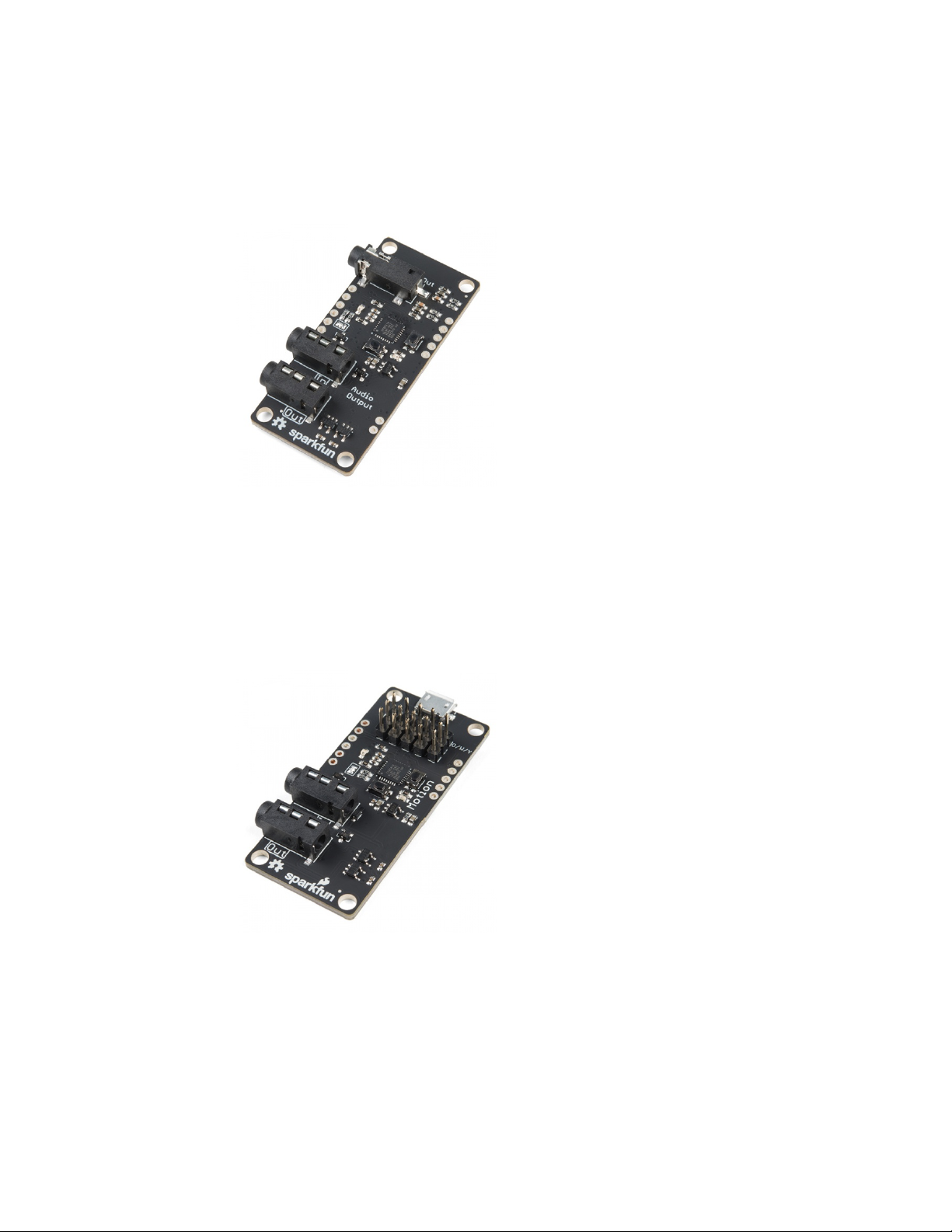
Audio Output Board
The Audio Output Board adds the ability to play sounds from a Micro SD
card to your Spectacle system. It provides a line-level output ready to be
amplified.
Motor Control Board
The Motor Control Board is made to drive conventional hobby servo
motors, either normal type or continuous rotation type. It can be powered
via the Director Board connection or via a local input port for higher power
servo motors.
Light Board
Spectacle Audio Boar
d
DEV-14034
Spectacle Motion Boar
d
DEV-13993
Page 2 of 1
6
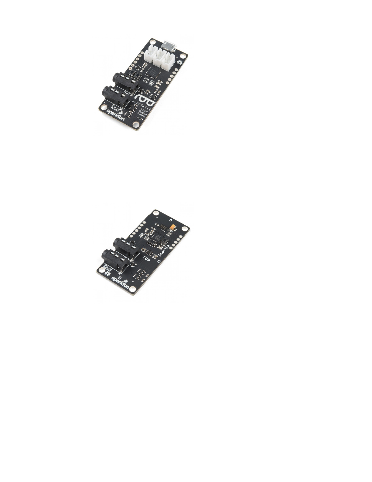
The Light Board controls strands of addressable LEDs, allowing it to realize
quite a few interesting effects that otherwise wouldn’t be possible.
Inertia Sensing Board
The Inertia Sensing Board allows you to trigger events on motion, stillness,
or orientation.
Button Input Board
Spectacle Light Boar
d
DEV-14052
Spectacle Inertia Boar
d
DEV-13992
Page 3 of 1
6

The Button Input Board takes its input from all manner of button, switches,
or other contact type sensing devices. It has 8 external inputs and one
onboard button, allowing for a large number of inputs to a single module.
Spectacle Director Board
The Spectacle Director Board is at the core of all Spectacle systems. It
stores the program, connects to and sends power to the other boards in the
system, and passes messages between the other boards.
Director Board Hardware Tour
There are two buttons on the Director Board: one labeled RST and one
labeled PROG. These buttons allow you to enter programming mode, so
new behaviors can be loaded into your Spectacle system.
To enter programming mode, press and hold the RST button, press and
hold the PROG button, and then release the RST button.
Power for your Spectacle system is delivered via a Micro USB jack on the
Director Board. Power is then delivered to additional boards in the system
via the cables connecting the other boards together, although some boards
(such as the Motion Board and the Light Board) may require locally
delivered power.
Spectacle Button Boar
d
DEV-14044
Page 4 of 1
6

The “Program” jack is where you’ll connect the device you use for
programming. A cable connecting this jack to the audio output of your
programming device is needed to upload a new set of behaviors to your
Spectacle system.
Other Spectacle boards will be connected to the “Direct” jack. Power is
delivered via this jack to the other boards, and power to those boards is
disconnected while the RST button is held down.
Spectacle Example
Spectacle actions are mediated by “Channels”, which represent information
sent from input modules to output modules by way of the Director Board.
More than one board may listen to a single channel, and more than one
board may write to a single channel by use of “virtual” boards to combine
signals.
An Example
In our simple example, we’ve created a system with only two boards: the
Director Board and the Audio Output Board. This simple example is going
to play a sound at random intervals, with a minimum of 10 seconds
between playback.
Here we see the opening screen of the Spectacle App. The default name
(in this case) is “my talented project” but you can, of course, change this to
be anything that you’d like. We’ll just leave it as is. Next, we need to add
our Audio Output Board to the project. Click the “ADD A BOARD” button at
the bottom of the page.
Page 5 of 1
6

You’ll now see a list of the various types of boards which are currently
available. We’ve discussed five of these six entries, and we’ll cover what a
virtual board is in a second. For now, just click on “Audio” to add our Audio
Output Board.
We’re now back at the beginning screen, with the addition of another line
below the project info line for a “painstaking sound board”. You can rename
this as you please by simply clicking in the text field holding the board’s
name.
Now click the clapboard icon to bring up a list of actions assigned to the
board.
Page 6 of 1
6

Unsurprisingly, it’s empty. We have to add something! At the bottom of the
page, find the “ADD AN ACTION” button. Click it and a list of actions will
descend from the top of the page.
For the Audio Output Board, only two options exist: “Cancel” and “Play
Sound”. Click on “Play Sound” to add that action to our actions list.
Page 7 of 1
6

You’ll find this screen has appeared. There are four blanks, for four user
inputs, and a slider at the bottom which we’re going to ignore. Here are the
uses of the other fields.
* “Listen to channel number…” - This is the channel number which
triggers the audio to start playing. As long as this channel’s value is above
the threshold level (set by that slider that we’re not going to mess with), the
sound will repeat playing at a rate determined by the two time intervals
specified lower down.
* “wait … seconds and play…” - This is the first delay in the system. By
delaying when a sound plays, you can sequence events however you see
fit.
* “…and play file number…” - This is where you tell the board which file
to play. Remember, when copying the audio files to the Micro SD card, they
should be named as 00.ogg, 01.ogg, 02.ogg, etc. The number in this field
corresponds to the number in the name of the audio file. If there is no audio
file with the corresponding number, no sound will play.
* “do not allow another sound to interrupt until … seconds” - The
number in this field should correspond to the length of the audio file. If this
value is less than the length of the sound file, another trigger sent to the
audio board will interrupt the sound before it finishes. If it is longer than the
sound, there will be a period of silence after playback before another
playback can be initiated.
Page 8 of 1
6

Here are the settings to put into the fields. Note that we are listening on
channel 0, as we’ll need that information later. We want to play our
sound immediately, play sound file 00.ogg, and not interrupt that sound for
at least one second.
There! We’ve added the instruction to play back a sound. Now we need to
tell the system when to play the sound. Click the “GO BACK” button at the
bottom of the screen. Don’t worry, the action you added has been saved
automatically.
We’re back at the opening screen again, and you can see that “play sound
on channel 0” has been added to the Sound Board’s entry. If we had
created more actions, they would show up there, as well. Click the “ADD A
BOARD” button to continue.
Page 9 of 1
6

We’re back at the list of boards. This time, we’re going to add a virtual
board. This special subset of “boards” adds functionality that otherwise isn’t
added by any particular hardware board.
Now a virtual board entry appears in our project list. The Virtual Board entry
is special, in that it can only exist once in the boards list, and it will always
“sink” to the bottom of the list, even if you try to rearrange boards beneath it
or if you create boards after the virtual board. Again, click on the clapboard
icon to enter the add/edit actions view.
Page 10 of 1
6
Autres manuels pour Spectacle
1
Table des matières
Autres manuels sparkfun Contrôleurs


