\
INSTALLATION
WARNING: THESE PROCEDURES MUST BE FOLLOWED BY QUALIFIED
PERSONNEL OR WARRMJTY WILL BE VOIDED.
GENERAL:
The installation must conform with local codes, or in the absence of local codes, with the
National Fuel Gas Code, ANSI Z223.1-Latest Edition. Canadian installation must comply with
CAN/CGA-B149.1 Natural Gas Installation Code, Code CAN/CGA-B149.2 Propane Installation Code.
Canadian Electrical Code Parts I, or Local Codes and CSA C22.1
These models are for operation on natural or propane gases.
The appliance should be connected ONLY to the type of gas for which it is equipped. All Southbend
equipment is adjusted at the factory, however, burner air shutters and pilot heights should be checked
at installation and adjusted if necessary. Check type of gas on serial plate located on interior bottom. at
center towards front under ffease
fan.
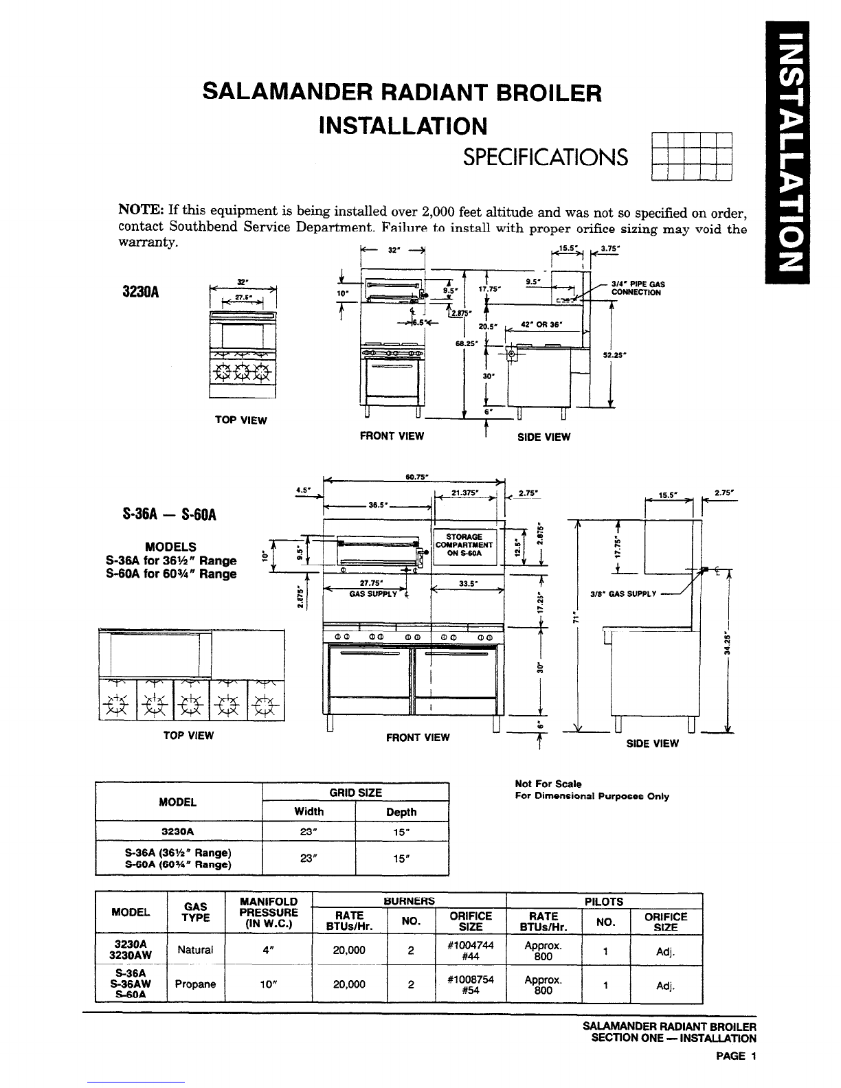
For orifice sizes and pressure regulator settings refer to chart under “specifications.”
An adequate gas supply is imperative. Undersized or low pressure lines restrict the volume of gas
necessary for satisfactory performance. A pressure regulator, which is provided with each unit, is set to
maintain a 4” W.C. manifold pressure for natural gas and a 10” W.C. manifold pressure for propane
gas. However, to maintain these conditions, the pressure on the supply line when all units are
operating simultaneously, should not drop below 7” W.C. for natural gas or 11” W.C. for propane gas.
All pipe joints should be tested for leaks with a soap and water solution before operating the unit. The
test pressure should not exceed 14” W.C.
CAUTION:
THIS APPLIANCE AND ITS INDIVIDUAL SHUTOFF VALVE MUST BE
DISCONNECTED FROM THE GAS SUPPLY PIPING SYSTEM DURING ANY
PRESSURE TESTING OF THAT SYSTEM AT TEST PRESSURES IN EXCESS OF 1I2
PSIG (3.45 EPA).
THIS APPLlANCE MUST BE ISOLATED FROM THE GAS SUPPLY PIPING SYSTEM BY
CLOSING ITS INDIVIDUAL MANUAL SHUTOFF VALVE DURING ANY PRESSURE
TESTING OF THE GAS SUPPLY PIPING SYSTEM AT TEST PRESSURES EQUAL TO
OR LESS THAN 1I2 PSIG (3.45 EPA).
If applicable, the vent line from the gas appliance pressure regulator shall be installed to the outdoors
in accordance with local codes or, in the absence of local codes, with the National Fuel Gas Code, ANSI
Z233.1-Latest Edition. Canadian installation must comply with CAN/CGA-B149.1 Natural Gas
Installation Code, Code CAN/CGA-B149.2 Propane Installation Code.
EXHAUST FANS AND CANOPIES:
Canopies are set over ranges, ovens, etc., for ventilation
purposes. It is recommended that a canopy extend 6” past appliance and be located 6’6” from the floor.
Filters should be installed at an angle of 45” or more with the horizontal. This prevents dripping grease
and facilitates collecting the run-off grease in a drip pan, usually installed with a filter. A strong
exhaust fan tends to created a vacuum in the room and may interfere with burner performance or may
extinguish pilot flames. Fresh air openings approximatelv equal to the fan area will relieve such
vacuum. In case of unsatisfactory performance on any appliance, check with the exhaust fan in the
“OFF” position.
WALL EXHAUST FAN:
Should be installed at least two feet above the vent opening at the top of the
shelf or backsplash.
NOTE: Due to the variety of problems encountered by outside weather conditions, venting by canopies
or wall fans is preferred over any type of direct venting.
INSTALMTION:
NOTICE: THERE MUST BE ADEQUATE CLEARANCE BETWEEN
UNITS AND COMBUSTIBLE CONSTRUCTION. CLEARANCE MUST
ALSO BE PROVIDED FOR SERVICING AND FOR OPERATION.
WARNING: ALL UNITS MUST BE INSTALLED IN SUCH A MANNER THAT THJi’ FLOW
OF COMBUSTION AND VENTILATION AIR ARE NOT OBSTRUCTED. PROVISIONS
FOR AN ADEQUATE AIR SUPPLY MUST ALSO BE PROVIDED. DO NOT OBSTRUCT
TBE FRONT OF THE UNIT AS COMBUSTION AIR ENTERS THROUGH THIS AREk
SALAMANDER RADIANT BROILER
SECTION ONE - INSTALLATION
PAGE 2
Litho m U.S.A.
2-94