!
WARNING
This product contains high intensity LED
devices. To prevent eye damage, DO NOT
stare into light beam at close range.
EPRDSGS1(x) 02/08
BY SOUNDOFF SIGNAL
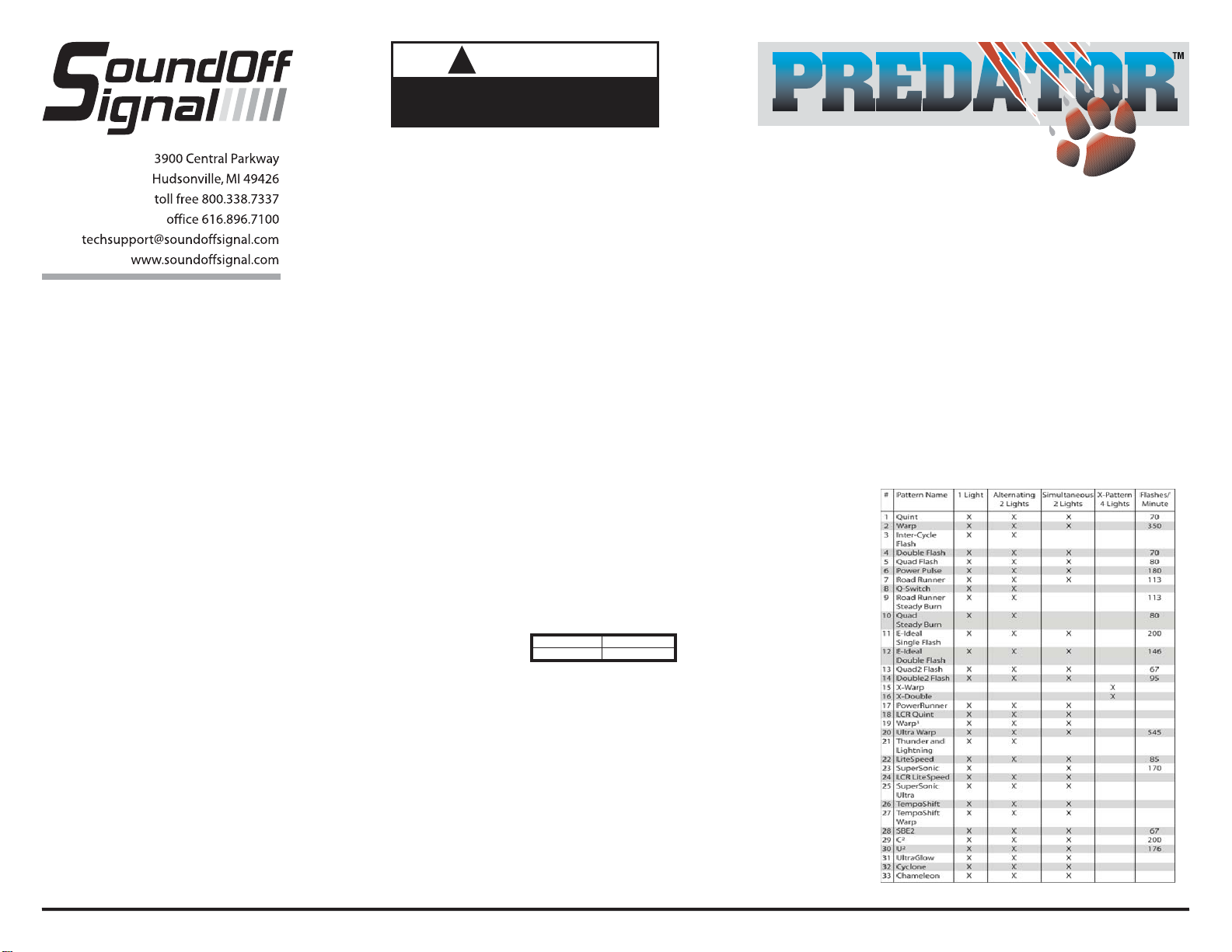
FLASH PATTERNS for
SINGLE HEAD EXTERIOR PREDATOR II (EP2SGS1(x))
X-Pattern Sequence
ID#1 > ID#4 > ID#2 > ID#3
X-Pattern Light Head Placement
ID#4 ID#2
ID#3 ID#1
Predator Sync Configuration Instructions
1. Set ID#
a. Identify which pattern and sequence you want and look up ID#s on table.
b. Connections
i. RED: +12Vdc
ii. WHT: +12Vdc (Note: you will need to disconnect after power is applied)
iii. BLK: Ground
c. Apply power to unit
d. Without disconnecting power from unit, disconnect WHT wire
e. Momentarily connect WHT to Ground to change ID #
i. Identify ID# by number of sequential flashes
ii. Possible ID#s: 1 – 4
f. Disconnect power from unit to get out of ID mode.
2. Set Pattern
a. Reapply power to units.
b. Once all Light Head ID#s are configured, make sure all lights are flashing the
same pattern
c. Connect corresponding colored wires of all units together: RED to RED, etc.
d. Change Pattern
i. Momentarily connect WHT wires to Ground
ii. Observe pattern change on all lights connected
e. Insulate all wires by taping with electrical tape
3. Connect Master Switch for Application
a. IMPORTANT! Ensure WHT Pattern/Sync Wires are tied together
1LIGHT
Single Light Operation: Follow the ID Selection steps and set the LED3 to ID#1 if it is not already. NOTE: Steady
Burn is produced for patterns 9 & 10 in Single Operation.
2 LIGHTS
ALTERNATING: To obtainAlternating patterns, follow the ID SELECTION steps and set one LED3 to ID#1 and the
other to ID#3. Then proceed to the PATTERN SELECTION steps.
SIMULTANEOUS: To obtain Simultaneous patterns, follow the ID SELECTION steps and set both LED3 lights to
ID#1. Then proceed to PATTERN SELECTION steps.
4 LIGHTS
X-Pattern: To obtain X-patterns, follow the ID SELECTION steps and set one of the four LED3 lights to ID#1, one
to ID#2, one to ID#3, and one to ID#4. Then proceed to PATTERN SELECTION steps. NOTE: Be sure to mount
each LED3 in the correct placement based on ID#.
SLAVE MODE
The LED3 is capable of being activated through the use of a
user supplied flasher by putting it in slave mode.
1. Permanently connect the LED3 WHITE and BLACK wire to a
good, convenient ground.
2. Connect the LED3 RED wire, through a 5Amp fuse, to the
output of a +10-30Vdc switching flasher.
NOTE: The LED3 is a factory sealed unit that CANNOT be
serviced in the field. Any attempt to gain access to the LED3
unit will most likely cause permanent damage and void its
warranty.
PATTERN SELECTION
1. Disconnect WHITE wire from any
connections if applicable.
2. Turn PREDATOR II ON.
3. Momentarily touching and removing the WHITE
wire(s) to ground
will advance the PREDATOR II to the next flash
pattern. Touching and
removing the White wire for more than a few seconds
will allow you to change the PREDATOR II to the
previous pattern. See flash pattern table. Continuing
to touch and remove the WHITE wire(s) to ground will
allow you to scroll through the pattern list. After pattern
#33 is reached the list will start over again at pattern
#1.
NOTE: The PREDATOR II is equipped with flash
pattern memory. Once you have selected a pattern the
PREDATOR II will always activate to that pattern
every time the unit is turned on. Tape up and secure
WHITE wire so that it will not accidentally change your
selected pattern
PATTERN RESET
1. Remove power.
2. Place WHITE (sync) wire to ground.
3. With sync wire grounded, re-power RED wire.
4. Maintain for one second (light will dim).
5. Remove power and ground (pattern 1 set)..
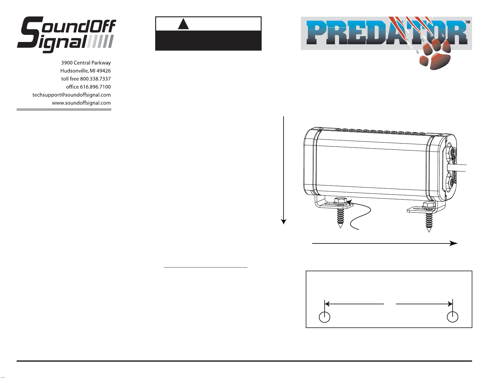
SINGLE EXTERIOR
DECK / GRILLE
WARNING SYSTEM
ASSEMBLY INSTRUCTIONS
EPRDSGS1(x)