ELECTRICAL CONNECTIONS
Access Terminal Compartment
Wall Mounting Wiring
N L E
N = Neutral
L = Live
E = Earth
AVS3P-0
To Equipment
A1
A2
CC
O
T
T1
L1 L2
T2 T3
L3
Contactor
1 2 3 4
1 2 3 4
OFF OFF
ON ON
SENSE WIRES FROM
LOAD CONTACTOR (INPUT SIDE)
1) Connect sensing cables from L1 to
R, L2 to S and L3 to T. Connect the
neutral to A2 and N.
The output from the AVS3P is a
changeover relay with volt-free contacts.
• Good Voltage: C connects to NO
• Bad Voltage/wait mode: C connects
to NC
2a) Contactor
• Connect NO to A1
• Connect C to L1
2b) Control Circuit
• Connect NO to A1
• Connect C to the external
controller/control circuit
2c) Remote Monitoring
• Connect NC to the stop control
• Connect NO to the start control
• Connect C to the 24 Vdc supply
REPAIR/MAINTENANCE
The internal surge protection fuse may
blow during a severe surge.
Only a qualied person should carry out
repairs. Ensure power is isolated.
1) Remove the terminal cover.
Access Terminal Compartment
Wall Mounting Wiring
N L E
N = Neutral
L = Live
E = Earth
AVS3P-0
From Mains
To Equipment
A1
A2
Contactor
1 2 3 4
1 2 3 4
OFF OFF
ON ON
SENSE WIRES FROM
LOAD CONTACTOR (INPUT SIDE)
2) Ensure to replace the fuse with a fuse
of the same type and rating: 5.0A
HBC anti-surge fuse (20x5mm).
ENABLE ADDITIONAL PROTECTION
Phase rotation, voltage phase imbalance
& frequency error, can be enabled via the
switches inside the top compartment.
Ensure power is isolated before
removing the top cover.
Access Terminal Compartment
Wall Mounting Wiring
N L E
N = Neutral
L = Live
E = Earth
AVS3P-0
From Mains
To Equipment
A1
A2
Contactor
1 2 3 4
1 2 3 4
OFF OFF
ON ON
SENSE WIRES FROM
LOAD CONTACTOR (INPUT SIDE)
1) Remove the 4 screws from the rear of
the unit and then remove the cover.
Access Terminal Compartment
Wall Mounting Wiring
N L E
N = Neutral
L = Live
E = Earth
AVS3P-0
From Mains
To Equipment
A1
A2
1 2 3 4
1 2 3 4
OFF OFF
ON ON
SENSE WIRES FROM
LOAD CONTACTOR (INPUT SIDE)
2) Turn ON the required function(s) by
sliding the switch from right to left.
3) Replace and secure the top cover
before powering ON.
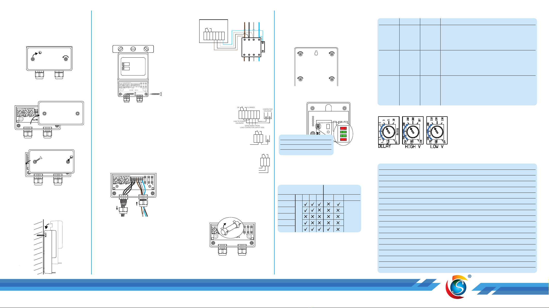
SETTING CHANGE
Dial Range Default Description
Delay
Time
OFF, 30
sec to 10
min
3 min The duration that the AVS3P will monitor the voltage
before connecting it to your equipment after start-up or a
disconnection period caused by high or low voltage.
If set to OFF, the power will be connected to your
equipment after a 10 second sensing delay.
High
Voltage
230 V to
300 V, OFF
260 V The maximum voltage that the AVS3P will still power your
equipment. The AVS3P will disconnect the equipment
from the supply when the voltage exceeds this set value.
If set to OFF, the AVS3P will continue to supply the
equipment regardless of the voltage value.
Low
Voltage
OFF, 160 V
to 230 V
200 V The minimum voltage that the AVS3P will still power your
equipment. When the voltage falls below this set value,
the AVS3P will disconnect the equipment from the supply.
If set to OFF, the AVS3P will continue to supply the
equipment down to 150V (minimum working voltage),
below this, the AVS3P will disconnect the supply.
Note: Always match the set AVS3P limits to the equipment requirements.
SPECIFICATION
Nominal Voltage 230 V / 400 V
Maximum Supply Voltage 320 V
Current 16 A Max. (drives contactor solenoid)
Max Consumption 35 VA
Voltage Disconnect Off, 160 to 300 V (user settable)
Hysteresis (reconnection voltage) 3 V from set limits
Low Voltage Blind Time 1 s
High Voltage Blind Time 0.5 s
Wait Time OFF, 30 s to 10 min
Spike Protection 160 J
Mains Spike Discharge 6.5 kA
Spike Response Time <10 ns
Temporary Over Voltage (TOV) 415 V
Extra Voltage Protection Frequency, Phase Imbalance & Phase Rotation
Frequency 47 to 52 Hz & 57 to 62 Hz
Voltage Phase Imbalance Detection 4.8%
Connector Screw Terminals
Unit Dimensions 184 x 134 x 53 mm (without cable glands)
Unit Weight 500 g
TERMINAL COMPARTMENT
Within the Terminal compartment, there
are terminals for electrical connections,
unit mounting holes, and setting dials.
Isolate the power to the AVS3P before
removing the terminal cover.
Access Terminal Compartment
Wall Mounting Wiring
N L E
N = Neutral
L = Live
E = Earth
AVS3P-0
From Mains
To Equipment
A1
A2
Contactor
1 2 3 4
1 2 3 4
OFF OFF
ON ON
SENSE WIRES FROM
LOAD CONTACTOR (INPUT SIDE)
1) Remove the screw hole covers.
2) Loosen the two xing screws and
remove them from the hole.
Access Terminal Compartment
Wall Mounting Wiring
N L E
N = Neutral
L = Live
E = Earth
AVS3P-0
From Mains
To Equipment
A1
A2
Contactor
1 2 3 4
1 2 3 4
OFF OFF
ON ON
SENSE WIRES FROM
LOAD CONTACTOR (INPUT SIDE)
3) Lift the terminal cover to remove it.
Access Terminal Compartment
Wall Mounting Wiring
N L E
N = Neutral
L = Live
E = Earth
AVS3P-0
From Mains
To Equipment
A1
A2
Contactor
1 2 3 4
1 2 3 4
OFF OFF
ON ON
SENSE WIRES FROM
LOAD CONTACTOR (INPUT SIDE)
4) Replace and secure the terminal
cover before powering ON.
MOUNTING
1) Mark and drill the top mounting hole
Access Terminal Compartment
Wall Mounting Wiring
N L E
N = Neutral
L = Live
E = Earth
AVS3P-0
From Mains
To Equipment
A1
A2
Contactor
1 2 3 4
1 2 3 4
OFF OFF
ON ON
SENSE WIRES FROM
LOAD CONTACTOR (INPUT SIDE)
2) Use an appropriate wall xing to
fasten a screw into the hole, leaving
the screw extruding about 10 mm.
3) Hang the AVS on the protruding
screw using the notch on the back of
the AVS3P.
Access Terminal Compartment
Wall Mounting Wiring
N L E
N = Neutral
L = Live
E = Earth
AVS3P-0
From Mains
To Equipment
A1
A2
Contactor
1 2 3 4
1 2 3 4
OFF OFF
ON ON
SENSE WIRES FROM
LOAD CONTACTOR (INPUT SIDE)
4) Ensure the unit is level before
marking and drilling the two bottom
mounting holes.
5) If wall xings are required, remove
the AVS3P from the wall and insert
xings into the wall. Replace the
AVS3P on the top screw.
6) Tighten 2 screws into the bottom
mounting holes to secure the AVS3P
to the wall.
AVS3P WIRING
Access Terminal Compartment
Wall Mounting Wiring
N L E
N = Neutral
L = Live
E = Earth
AVS3P-0
From Mains
To Equipment
A1
A2
Contactor
1 2 3 4
1 2 3 4
OFF OFF
ON ON
SENSE WIRES FROM
LOAD CONTACTOR (INPUT SIDE)
1) Insert the wires through the gland
nut and the glands.
2) Connect the corresponding wires to
the AVS3P terminals.
3) Tighten the cable gland nuts and
secure the terminal cover in place.
1Phase Rotation Error
2Phase Imbalance Error
3Frequency Error
4Not Connected
Access Terminal Compartment
Wall Mounting Wiring
N L E
N = Neutral
L = Live
E = Earth
AVS3P-0
From Mains
To Equipment
A1
A2
A1
CC
O
Contactor
1 2 3 4
1 2 3 4
OFF OFF
ON ON
SENSE WIRES FROM
LOAD CONTACTOR (INPUT SIDE)
Access Terminal Compartment
Wall Mounting Wiring
N L E
N = Neutral
L = Live
E = Earth
AVS3P-0
From Mains
To Equipment
A1
A2
CC
O
Contactor
1 2 3 4
1 2 3 4
OFF OFF
ON ON
SENSE WIRES FROM
LOAD CONTACTOR (INPUT SIDE)
Notes:
•
WAIT LED indicates alarm level clearance
(10s or user-selected DELAY timeout).
•
If Delay is OFF, default 10-second delay is
automatically activated.
•
If LVD is OFF, only default 150V fast OFF is
active.
•
If HVD is OFF, no high-level voltage protection.
Turn the dial with a small
screwdriver or your thumb to
make necessary adjustments.
Access Terminal Compartment
Wall Mounting Wiring
N L E
N = Neutral
L = Live
E = Earth
AVS3P-0
From Mains
To Equipment
A1
A2
Contactor
1 2 3 4
1 2 3 4
OFF OFF
ON ON
SENSE WIRES FROM
LOAD CONTACTOR (INPUT SIDE)
Optional Settings Standard Functions
(Dip switches 1 to 3, one at a time)
(Thumbwheel settings)
LED 4 3 2 1 LVD HVD DELAY
High. OFF
High. WAIT
ON
Low. WAIT
Low. OFF
No LED
indication
other than
WAIT.
Not Connected
Detection
Access Terminal Compartment
Wall Mounting Wiring
N L E
N = Neutral
L = Live
E = Earth
AVS3P-0
From Mains
To Equipment
A1
A2
Contactor
1 2 3 4
1 2 3 4
OFF OFF
ON ON
CC
O
T
A2 A1
SENSE WIRES FROM
LOAD CONTACTOR (INPUT SIDE)


