
Solido Eco Manuel utilisateur
Montageanleitung
DS020642/06.2017
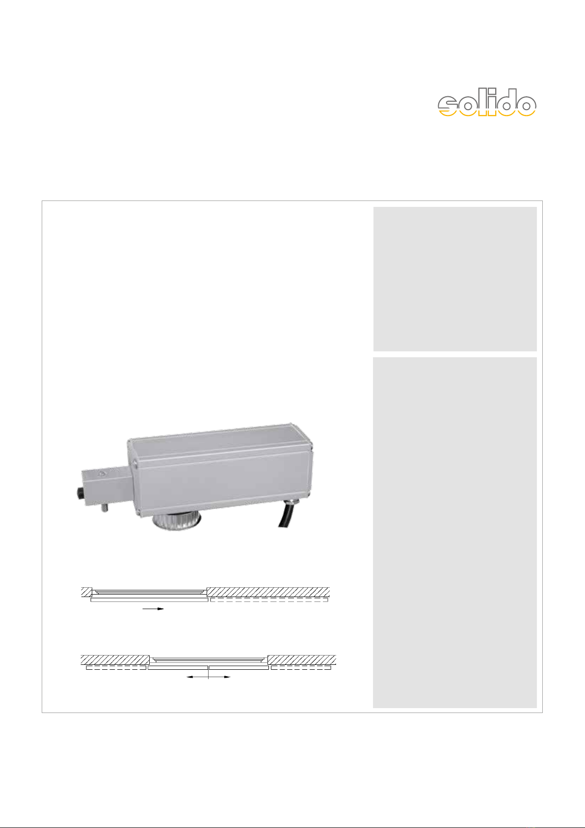
solido 80
Holz
mit Antrieb solido ECO
für ein- und zweiflügelige
Anlagen
solido 80
timber
with drive solido ECO for
single and double leaf doors
2
DS020642/06.2017
SW 10,
13, 17
Allgemeine Informationen
Benötigtes Werkzeug Seite 2
Lieferumfang Seite 3
Montage
Montageschritte ein- und zweiflügelig Seite 4
Schiebetürbeschläge
Solido 80 Holz Seite 7
bis 80 kg Flügelgewicht
Technische Hinweise
Einbauzeichnungen Antrieb solido ECO Seite 8
Montageanleitung Solido ECO Seite 11
General Information
Required tools Page 2
Scope of supply Page 3
Assembly
Mounting steps single and double door Page 4
Sliding door hardware
Solido 80 timber Page 7
up to 80 kg leaf weight
Technical notes
Mounting drawings drive solido EC Page 8
Installation instructions Solido ECO Seite 11
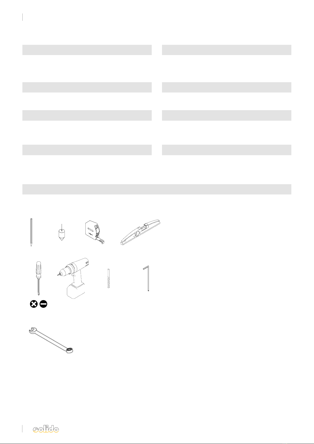
Benötigtes Werkzeug
Required tools
Größe/Size 3,
4 und/and 5
Größe/Size 6
und/and 8
Solido 80 Holz/Solido 80 timber
Inhalt/Content
3
DS020642/06.2017
General Information
Required tools Page 2
Scope of supply Page 3
Assembly
Mounting steps single and double door Page 4
Sliding door hardware
Solido 80 timber Page 7
up to 80 kg leaf weight
Technical notes
Mounting drawings drive solido EC Page 8
Installation instructions Solido ECO Seite 11
Solido 80 Holz/Solido 80 timber
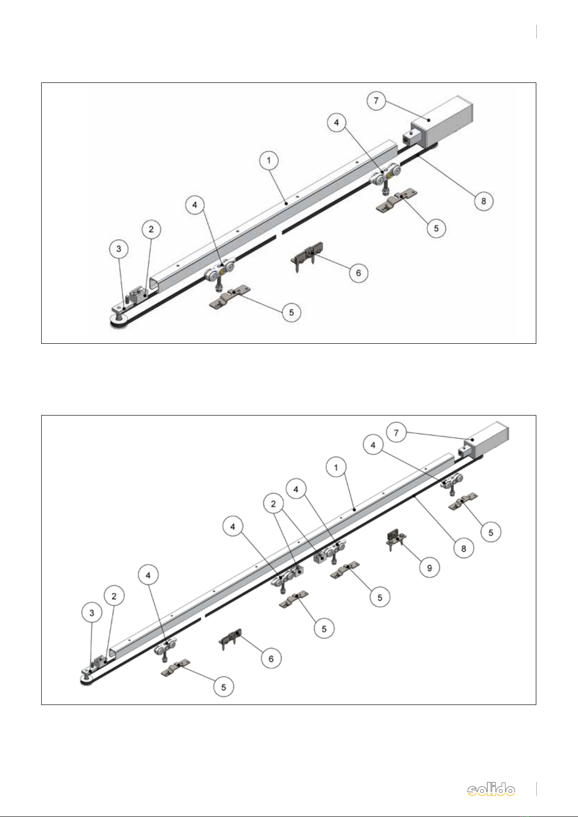
Lieferumfang/Sope of delivery
1. Laufschiene
2. Stopper
3. Umlenkrolle
4. Rollapparat
5. Flansch
1. Track
2. End Stop
3. Deflection roll
4. Trolley
5. Flange
6. Zahnriemenverbinder
7. elektrischer Antrieb
8. Zahnriemen
6. Toothed belt connector
7. elektrical drive
8. Tooth belt
Abb. 1 einflügelig/ fig. 1 single leaf
Abb. 2 zweiflügelig/ fig. 2 double leaf
1. Laufschiene
2. Stopper
3. Umlenkrolle
4. Rollapparat
5. Flansch
6. Zahnriemenverbinder
1. Track
2. Endstop
3. Deflection roller
4. Trolley
5. Flange
6. Toothed belt connector
7. elektrischer Antrieb
8. Zahnriemen
9. Zahnriemenmitnehmer
7. elektrical drive
8. Tooth belt
9. Tooth belt clamp

4
DS020642/06.2017
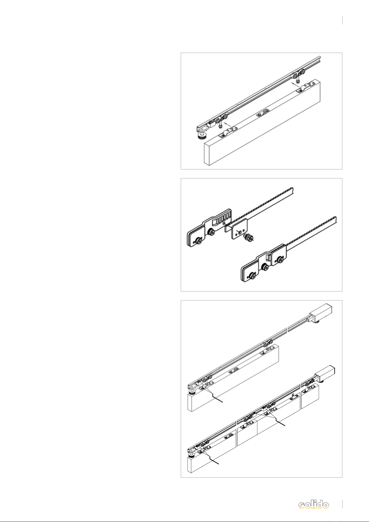
1. Laufschiene entsprechend der vorliegenden Befesti-
gung montieren. Die entsprechenden Einbauschnitte
finden Sie auf Seite 7.
1. Mount the track as it is appropriate for the used
mounting parts. The relevant sections can be found
on page 7
2. Rollen, Stopper und Umlenkrolle in die Laufschiene
schieben. Hierbei ist auf die Ausrichtung der Rollap-
parate zu achten (siehe Abb. 3 und Abb. 15).
(Achtung: Bei der zweiflügeligen Ausführung
kommen 2 Stopper in die Mitte.)
2. Push rolls, stops and deflection roll into the track.
While doing this, mind the orientation of the trolley
(see fig. 3 and fig. 15). (Attention: In case of the
double leaf type 2 stops are put in the middle.)
3. Antrieb mit passendem Adapter am Ende der Lauf-
schiene einsetzen und Gewindestift anziehen.
3. Put drive with suitable adapter at the end of the
track and tighten grub screw.
4. Flansche mittig der Flügelstärke auf der Schiebe-
tür befestigen. Die entsprechenden Abstände finden
Sie auf Seite 8 (Abb. 15).
4. Fix flange in the centre of the door gauge on the
sliding door. The relevant clearances can be found on
page 8 (fig. 15).
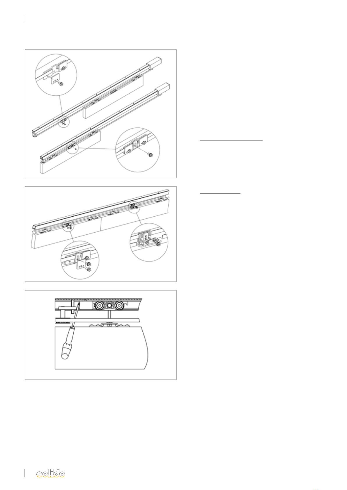
5. Zahnriemenverbinder: Befestigungsplatte vom
Winkel abschrauben. Winkel zwischen den
zwei Flanschen mittig auf der Schiebetür mittels
den beiliegenden Schrauben montieren.
5. Toothed belt connector: Unscrew fixing plate from
bracket. Mount bracket between the two flanges in
the centre on the sliding door using the enclosed
screws.
5a. Zweiflügelige Ausführung:
Mitnehmer: Befestigungsplatte vom Winkel ab-
schrauben. Winkel zwischen den zwei Flanschen
mittig des zweiten Flügels wie in Abb. 6 dargestellt
mittels der beiliegenden Schrauben montieren.
5a. Double leaf type:
Driver: Unscrew fixing plate from bracket. Mount
bracket between the two flanges, as shown in fig. 6,
in the centre on the sliding door using the enclosed
screws.
Abb. 4
Abb. 5
Abb. 3
Abb. 6
Solido 80 Holz/Solido 80 timber
Montageschritte, ein- und zweiflügelig/Mounting steps, single and double leaf
fig. 3
fig. 4
fig. 5
fig. 6
5
DS020642/06.2017
Abb. 7
Abb. 8
Abb. 9
Solido 80 Holz/Solido 80 timber
Montageschritte, ein- und zweiflügelig/Mounting steps, single and double leaf
fig. 7
fig. 9
fig. 8
6. Schiebetür in die Tragschrauben der Rollapparate
einhängen, Höhe (s. Seite 7) einstellen und Konter-
mutter anziehen.
6. Hang sliding door into the holding screws of the
trolley hangers, height (see page 7), set and tighten
counter screw.
7. Ein Ende des Zahnriemens in die Ausnehmung
der Befestigungsplatte einlegen und mit der Platte
klemmen.
7. Put one end of the toothed belt into the cut of the
fixing plate and clamp with the plate.
8. Schiebetür in beide Endstellungen verfahren.
Stopper und Umlenkrolle positionieren und die
Gewindestifte anziehen.
8. Move sliding door into both end positions. Position
stops and deflection roll and tighten grub screws.
6
DS020642/06.2017
Abb. 10
Abb. 11
Abb. 12
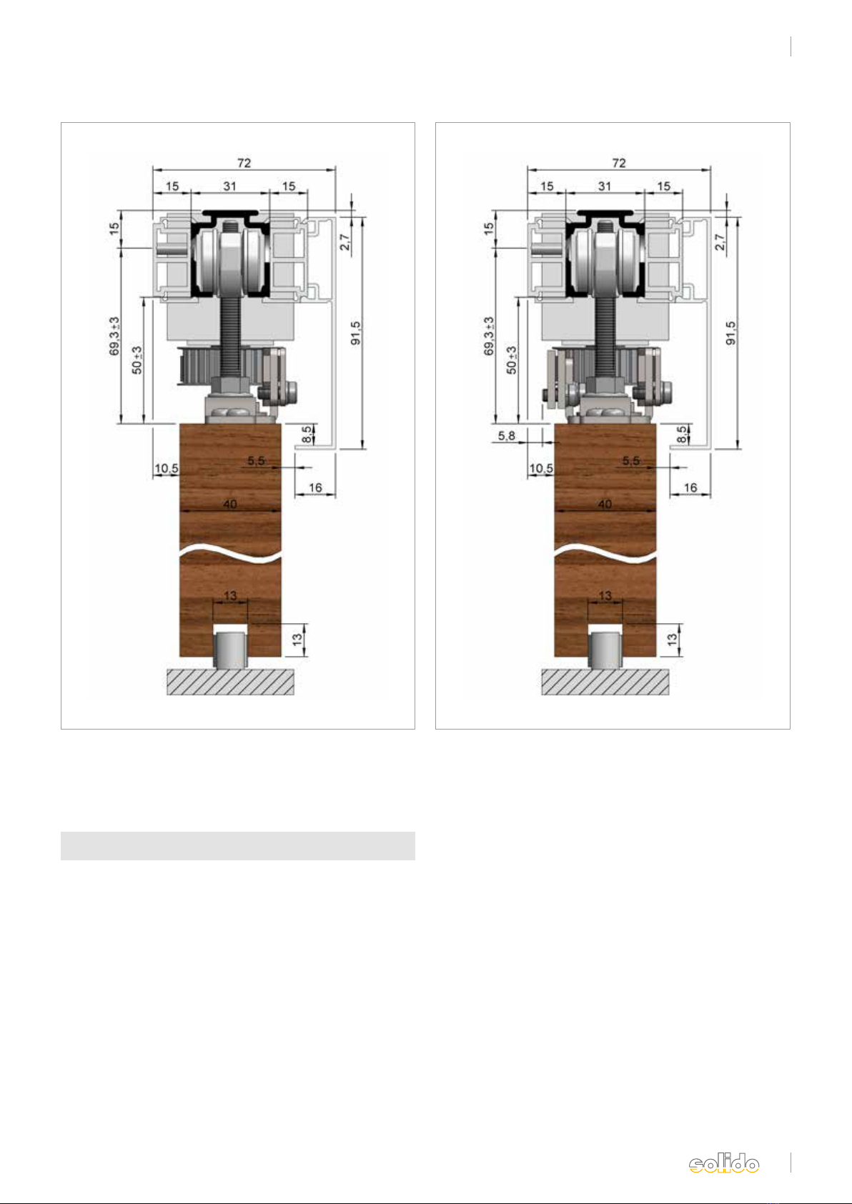
9. Zahnriemen um Antriebsritzel und Umlenkrolle
führen und mit Vorspannung in die andere Aus
nehmung der Befestigungsplatte einsetzen und mit
der Platte klemmen.
9. Guide toothed belt around drive pinion and
deflection roll and with pretension, put it into the
other cut of the fixing plate and clamp with plate
10. Befestigungsplatte mit Zahnriemen an dem Befesti-
gungswinkel verschrauben.
10. Befestigungsplatte mit Zahnriemen an dem Befesti-
gungswinkel verschrauben.
10a. Zweiflügelige Ausführung:
Schiebetüren in die geschlossene Endstellung ver-
fahren. Zahnriemen um Antriebsritzel und Umlenk
rolle führen und mit Vorspannung in die andere
Ausnehmung der Befestigungsplatte einsetzen und
mit der Platte klemmen.Befestigungsplatte des
Mitnehmers mit Zahnriemen verbinden und an
dem Befestigungswinkel verschrauben.
10a. Double leaf type:
Move sliding doors into the closed end position.
Guide toothed belt around drive pinion and
deflection roll and with pretension, put it into the
other cuts of the fixing plate and clamp with plate.
Join fixing plate of driver with toothed belt and
screw it on the fixing bracket.
11. Die Umlenkrolle lösen und mit Hilfe eines Schrau-
bendrehers, der zwischen Stopper und Umlenkrolle
angesetzt wird, den Zahnriemen spannen. Der
Zahnriemen sollte sich noch leicht zusammen-
drücken lassen.
11. Loosen deflection roll and tension the toothed belt
by means of a screwdriver that is applied between
stop and deflection roll. It should be possible to
press the toothed belt slightly together.
.
fig. 10
fig. 11
fig. 12
Solido 80 Holz/Solido 80 timber
Montageschritte, ein- und zweiflügelig/Mounting steps, single and double leaf
7
DS020642/06.2017
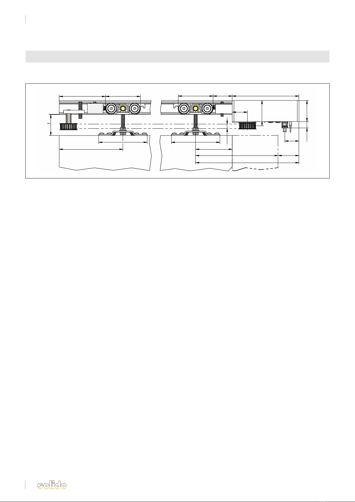
Abb. 13 Abb. 14
fig. 14
fig. 13
Solido 80 Holz/Solido 80 timber
bis 80 kg Flügelgewicht/up to 80 kg leaf weight
Abb. 13: Solido 80 Holz mit Antrieb solido ECO,
einflügelig bis 80 kg, elektrisch
Fig. 13: Solido 80 timber with drive solido ECO,
single leaf up to 80 kg, electrical
Abb. 14: Solido 80 Holz mit Antrieb solido ECO,
zweiflügelig bis 70 kg, elektrisch
Abb. 14: Solido 80 timber with drive solido ECO,
double leaf up to 70 kg, electrical
Solido 80 Holz mit Elektroantrieb
Solido 80 timber with electrical drive
8
DS020642/06.2017
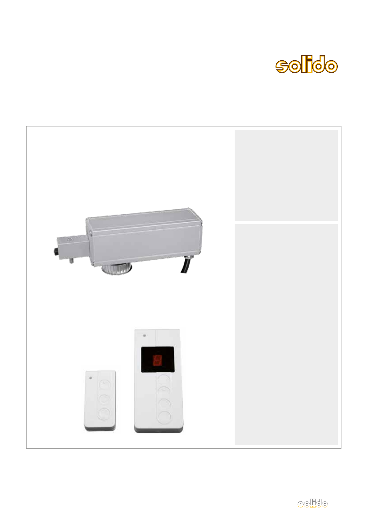
Einbauzeichnung Antrieb solido ECO/Mounting drawing drive solido ECO
solido 80
10
115
151
115
87
195,5 49,5
245
50
~
15
15845,582,8
~
110 82,8
50 3
36
60,5
33,5
Abb. 15
Solido 80 Holz/Solido 80 timber
Antrieb solido ECO/electrical drive solido ECO
fig. 15
DS020642/06.2017
Solido ECO
sliding door drive
Montageanleitung
Installation instructions
Solido ECO
Schiebetürantrieb

10
DS020642/06.2017
1. Eigenschaften des Solido ECO
• Netzanschluss 230V (ca. 2,5 m Kabel)
• geeignet für Dauernetzbetrieb 230V
• Gehäuse (ca. 50 x 50 x 158 mm) mit Motor und
integrierter Steuerung
• integrierte Trennrelais geeignet für lange Steuerleitungen
• geeignet für Bussystem
• extern wird ein nicht verriegelter Serientaster benötigt
oder optional ein Funksender
• alle Motorfunktionen über den nicht verriegelten Serien-
taster einstellbar (z.B. Geschwindigkeitsumschaltung, Push &
Go-Betrieb, automatischer Zulauf usw.)
• Multifunktions-LED zur Statusanzeige
• Reversion bei Auftreffen auf Hindernis in Zu-Richtung
• TÜV-geprüft nach DIN EN 18650-2 Low-Energy
• Wenn kein Serientaster eingebaut wird benötigt man einen
Einstellhilfetaster
Solido ECO
Allgemeine Informationen/General information
1. Properties of the Solido ECO
• power supply 230V (approx. 2.5 m cable)
• suitable for continuous mains operation 230V
• housing (approx. 50 x 50 x 158 mm) with motor and
integrated control
• integrated cut-off relay suitable for long control lines
• suitable for bus system
• externally a non-interlocked two-circuit breaker is required or,
optionally, a wireless transmitter
• all modes of operation of the motor can be set by the non-
interlocked two-circuit breaker (e. g. speed change, Push & Go
operation, automatic closing etc.)
• multi-functional LED for status display
• reversion when an obstacle is detected during closing
• TÜV certified according to DIN EN 18650-2 Low Energy
• If no two-circuit breaker is installed, an
adjustment aid button switch is required
Ce manuel convient aux modèles suivants
1
Table des matières


