Solid State Logic SB 32.24 Manuel utilisateur


Network I/O Stagebox SB 32.24 User Guide Contents
Visit SSL at:
www.solidstatelogic.com
© Solid State Logic
All rights reserved under International and Pan-American Copyright Conventions
SSL®, Solid State Logic®, Total Recall®, Gravity® and Tempest®
are ® registered trademarks of Solid State Logic.
System T™, Live L300™, Live L500™, L500 Plus™, Blacklight™
are ™ trademarks of Solid State Logic.
Dante™ and Audinate™ are trademarks of Audinate Pty Ltd.
All other product names and trademarks are the property of their respective owners
and are hereby acknowledged.
No part of this publication may be reproduced in any form or by any means, whether mechanical or
electronic,without the written permission of
Solid State Logic, Oxford, OX5 1RU, England
As research and development is a continual process, Solid State Logic reserves the right to change
the features and specifications described herein without notice or obligation.
Solid State Logic cannot be held responsible for any loss or damage arising directly or indirectly from
any error or omission in this manual.
PLEASE READ ALL INSTRUCTIONS, PAY SPECIAL HEED TO SAFETY WARNINGS.
E&OE
June 2017
Document Revision History
FIRST VERSION
Revision 1.0
20th June 2017
Page 2 of 25

Network I/O Stagebox SB 32.24 User Guide Contents
TableofContents
Table of Contents 3
Introduction 5
Key Features: 5
SB 32.24 Front Panel 5
SB 32.24 Rear Panel 5
Mains Power Connections 6
Channel LEDs 6
Net A, Net B and H/W status LEDs 7
Hardware Connections: 8
Status & Reset (DHCP) 8
Dante Connection Examples 9
Gain-dependant source and gain-compensated splits available to master console 9
Gain-dependant source and gain-compensated splits available to both consoles (no
SFP’s fitted - external switch connected) 9
Gain-dependant source and gain-compensated splits available to both consoles
(SFP’s fitted). 10
Gain-dependant source available to master console, Gain-compensated split
available to secondary console. 10
Connecting a PC: 11
Network Connection 11
SSL Network I/O Controller PC application 11
IP Address 11
Linking/Unlinking Networks A and B 12
Software Control 13
The GUI 13
Network View 13
Inputs/Outputs 14
View Inputs 14
View Outputs 15
Ownership 16
Gain Compensation 17
Dante Controller 18
Dante Controller PC GUI 18
Appendix A – Physical specifications 19
Appendix B – Performance specifications 20
Mic/Line Inputs 20
Measurement Parameters 20
Line Outputs 21
Measurement Parameters 21
Digital Inputs 22
Page 3 of 25

Network I/O Stagebox SB 32.24 User Guide Contents
Introduction
Overview
SB 32.24 is a 5U, 40-input and 24-output Dante stagebox featuring 32 SuperAnalogue™ mic/line
inputs, 4 AES/EBU inputs, 16 analogue line outputs and 4 AES/EBU outputs. All analogue and AES
audio connectors are XLR-3 type.
SB 32.24 can be controlled remotely from SSL Live and System T consoles as well as from SSL’s
Network I/O Controller app for PC.
SB 32.24 is suitable for all high-quality AoIP applications of any scale. Redundant power, redundant
ruggedized etherCON Dante connection plus two user-specifiable SFP ports which provide network
extension or support a second independent Dante network complete the professional hardware
requirement.
KeyFeatures:
●Interface between studio/stage/recording-area and IP audio networks using Dante
●SSL SuperAnalogueTM Studio Grade preamps
●Gain-compensated Dante Split available on the same or on a separate (B) network
●Device and parameter ownership assignment to avoid control conflicts
●Redundant PSUs and Dante ports
●Redundant network extension ports
●Clear front panel indication – signal present, phantom power, channel attention on analogue
inputs
●Front facing XLR connections
●Network B SFP ports can be configured with RJ45 or optical LC connectors
SB32.24FrontPanel
SB32.24RearPanel
Page 5 of 25

Network I/O Stagebox SB 32.24 User Guide Contents
MainsPowerConnections
Each Stagebox includes redundant PSUs with IEC connectors; either supply can individually power
the unit. Ideally these should be connected to separate power circuits to provide redundancy of
incoming AC power.
●PSU LEDs are informational and are green in normal operation.
●A flashing red PSU LED indicates the failure of PSU 1
●A static red PSU LED indicates a failure of PSU 2
ChannelLEDs
●Analogue signal LEDs (SIG) are green above -42 dBFS and red at -0.1 dBFS (clipping).
●48V / ATT indicates Phantom Power and/or Attention depending on red, green, or flashing
combinations as follows:
●Red – phantom power on
●Green flashing – channel Attention active
●Green & red flashing – phantom power on &
channel Attention active
Note: The three holes above each of the XLR sockets are part of the unit’s ventilation. Do
not block (e.g. with tape!)
Page 6 of 25

Network I/O Stagebox SB 32.24 User Guide Contents
NetA,NetBandH/WstatusLEDs
A series of LEDs towards the right hand side of the front panel indicate statuses as follows.
Label
LED Status
Off
Green
Red
(priority over
flashing red)
Flashing Red
AES IN 1/2
ACT
Analogue inputs
25/26 in use
AES inputs 1/2
in use
N/A
N/A
H/W
N/A
All hardware
(fans etc.) good
Hardware fault - check software
AES IN 3/4
ACT
Analogue inputs
27/28 in use
AES inputs 3/4
in use
N/A
N/A
NET A
N/A
Dante network
A good
Dante A Pri
Fault
Dante A Sec
Fault
AES IN 5/6
ACT
Analogue inputs
29/30 in use
AES inputs 5/6
in use
N/A
N/A
NET B
N/A
Dante network
B good
Dante B Pri
Fault
Dante B Sec
Fault
AES IN 7/8
ACT
Analogue inputs
31/32 in use
AES inputs 7/8
in use
N/A
N/A
PSU
Unit not
powered
PSU 1 & 2 good
PSU 1 Fault
PSU 2 Fault
Page 7 of 25

Network I/O Stagebox SB 32.24 User Guide Contents
HardwareConnections:
DANTEConnections
SB 32.24 has two redundant sets of network connections. The Network A ports feature etherCON
ruggedised RJ45 connectors, and the Network B ports are SFP cages, which can be fitted with either
RJ45, Single-mode or Multi-mode LC fibre connectors.
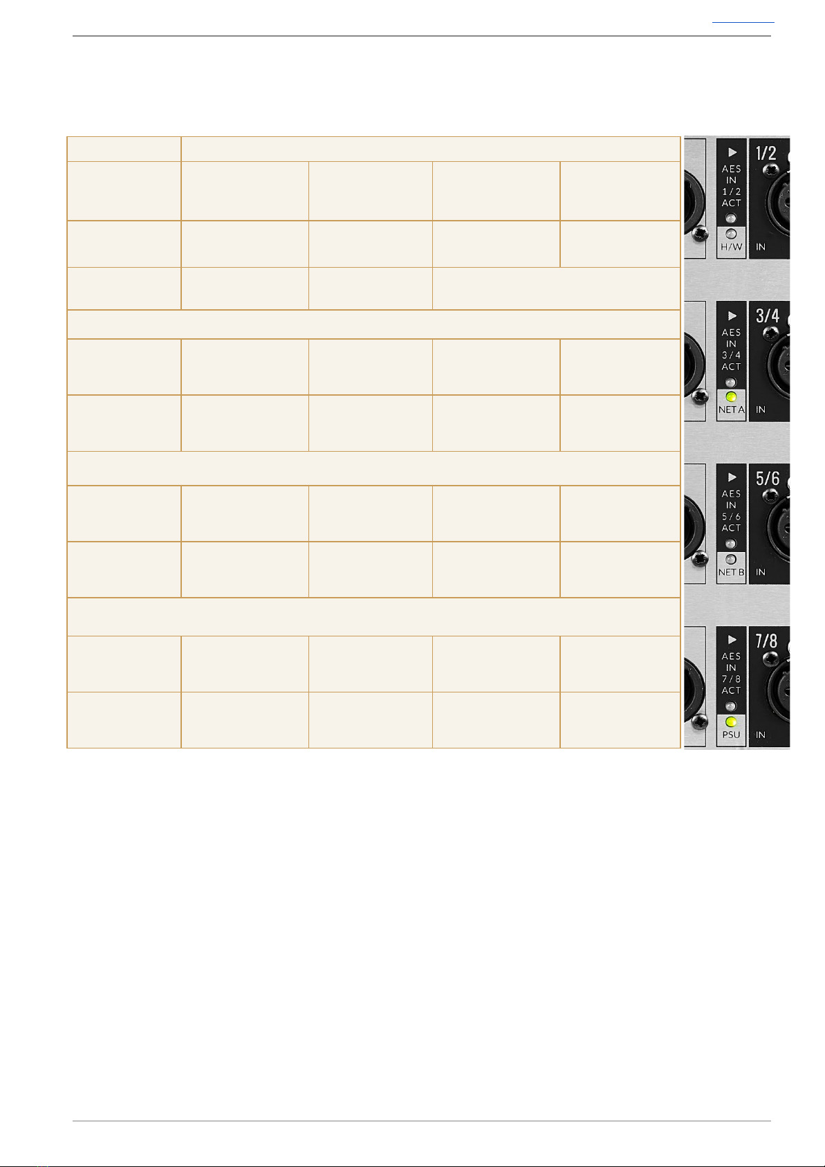
The SB 32.24 Network connections can be configured in two different modes:
In the first mode, the A and B networks are linked internally (A+B Network Link LEDs are ON). In
this mode, both Network A and Network B are identical and output both the gain-dependant and
gain-compensated audio. Dante devices can subscribe to either one.
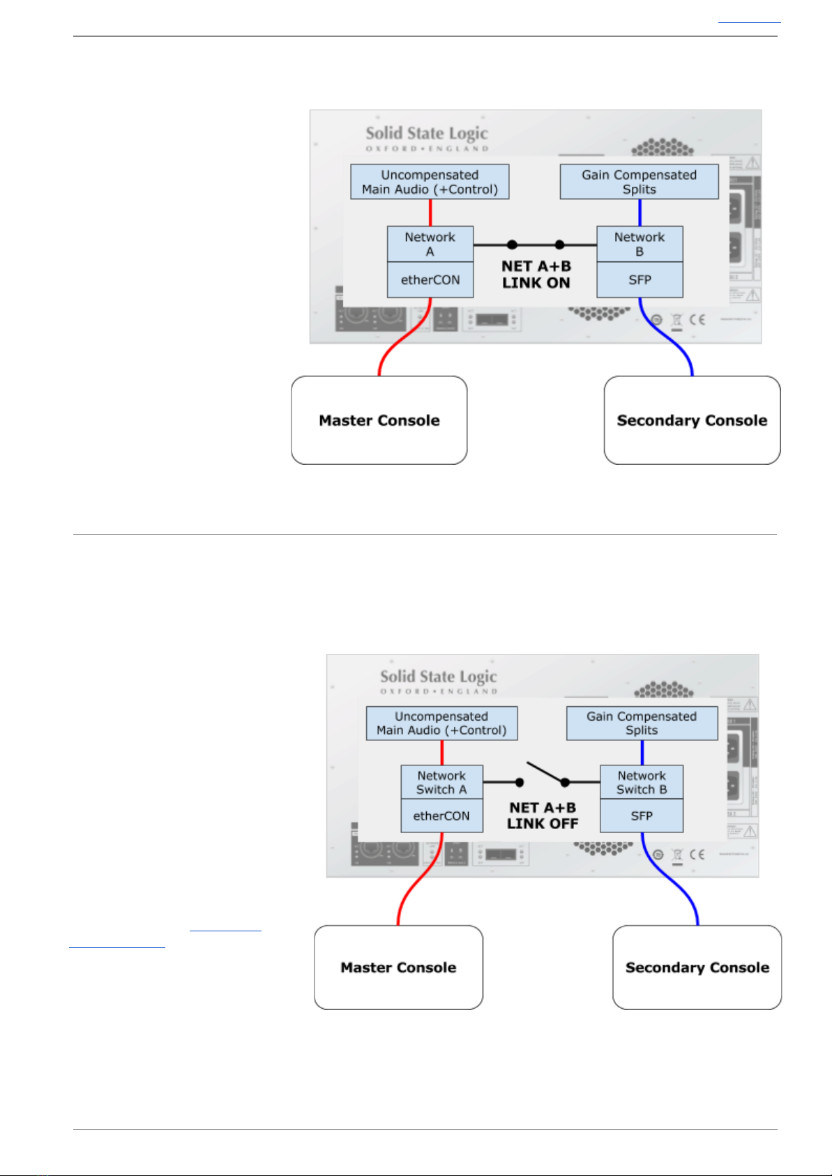
In second mode, the A and B networks are discrete (A+B Network Link LEDs are OFF), and
isolated from each other. In this mode Network A transmits uncompensated audio (and receives
audio for the analogue and AES outputs and also control data) and Network B transmits the
compensated audio only. Note that they have to be synchronised to the same clock source.
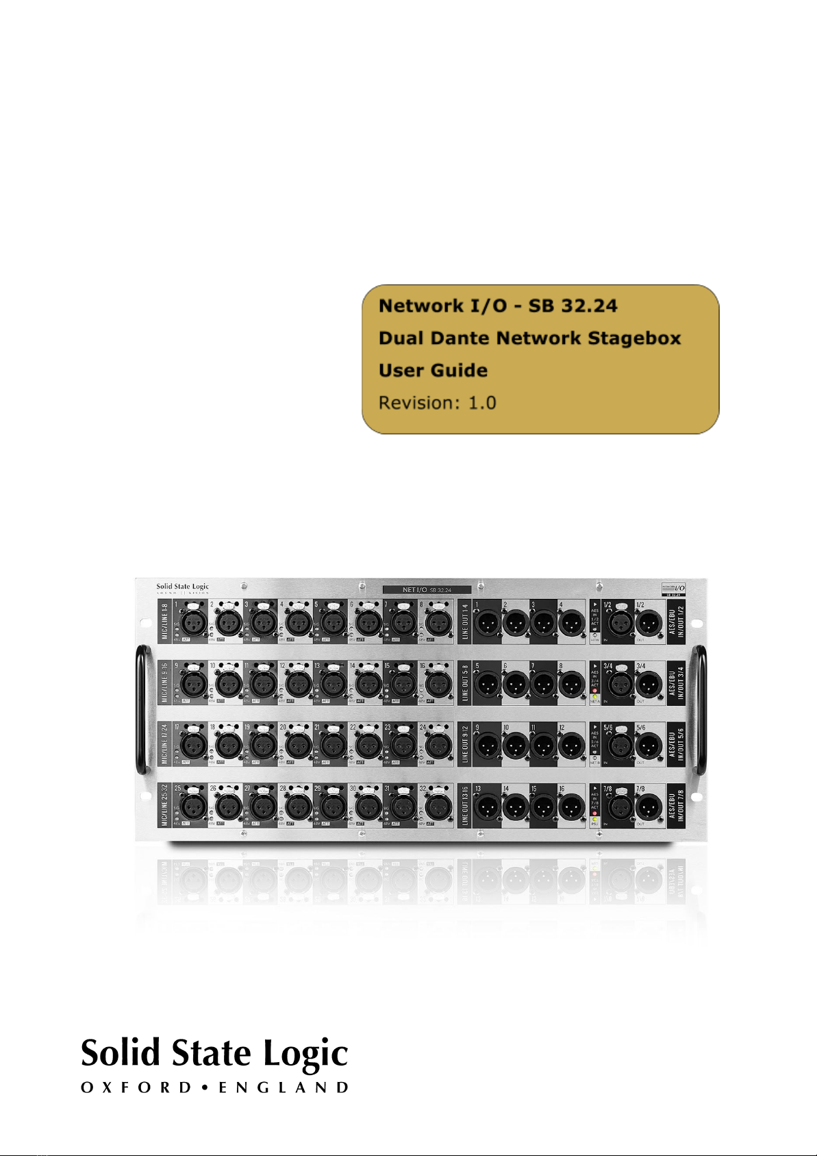
Status&Reset(DHCP)
A+B Network Link LED indicates unit is configured to connect internal
A and B networks
Off: Networks not linked
Green: Network A and Network B Linked
Dante B SRC LED is reserved for future possibilities!
Reset DHCP independently resets the internal Networks to DHCP
supplied addresses. Insert a small ‘prodder’ into the relevant opening
and press and hold for approx. 3 seconds to reset to DHCP addressing. The LED on the chosen port
will briefly turn red to indicate this has happened.
FactoryReset
If BOTH Reset DHCP buttons are held for 6 seconds, this will trigger a Factory Reset of the
stagebox.
Page 8 of 25

Network I/O Stagebox SB 32.24 User Guide Contents
DanteConnectionExamples
Gain-dependantsourceandgain-compensatedsplitsavailabletomasterconsole
In this mode, both the
gain-dependant and the
gain-compensated splits are
available to the master console.
Stagebox outputs are available to
the master console.
Gain-dependantsourceandgain-compensatedsplitsavailabletobothconsoles(noSFP’sfitted-
externalswitchconnected)
In this mode both the
gain-dependant and the
gain-compensated splits are
available to both consoles
(no SFP’s fitted - external
switch connected). Input
ownership and stagebox
outputs are available to
either console
Page 9 of 25

Network I/O Stagebox SB 32.24 User Guide Contents
Gain-dependantsourceandgain-compensatedsplitsavailabletobothconsoles(SFP’sfitted).
In this mode both the
gain-dependant and the
gain-compensated splits are
available to both consoles
(SFP’s fitted). Input
ownership and stagebox
outputs are available to
either console.
Gain-dependantsourceavailabletomasterconsole,Gain-compensatedsplitavailableto
secondaryconsole.
In this mode only the
gain-dependant split is available
to the master console. Only the
gain-compensated split is
available to the secondary
console. Input ownership and
stagebox outputs are only
available to the master console.
Please note: Secondary
console must be
synchronised to the same
clock source as the master
console.
To configure the internal
network link see NETWORK
CONNECTION later.
Page 10 of 25
Autres manuels pour SB 32.24
1
Table des matières
Autres manuels Solid State Logic Système d'E/S

Solid State Logic
Solid State Logic SSL SDI Manuel utilisateur

Solid State Logic
Solid State Logic MadiXtreme Manuel utilisateur

Solid State Logic
Solid State Logic Alpha-LinK MX 4-16 Manuel utilisateur

Solid State Logic
Solid State Logic A16.D16 Manuel utilisateur

Solid State Logic
Solid State Logic MadiXtreme MADI I/O Manuel utilisateur

Solid State Logic
Solid State Logic Multichannel Digital Audio Interface... Manuel utilisateur


