SolarVenti SV30AWX Manuel du propriétaire

Installation and Operation of
SV30AWX with 100 L Cylinder
Solar Heating System for Fresh Air and Domestic Hot Water
with 12V Solar Cell Operated P mp and Fan
See separate instr ctions for wall or roof mo nting of the standard SV30.
(These manuals also describe the regulator unit and air heating system.)
July 2011HJC
S
olarVenti
…..
at your sunny service

2
1.0 Contents
…………….………………………………………………………………. 3
1.1 The S 30AWX Principle …………………………………………………………… 4
1.2 An S 30AWX solar collector on the roof …………………………………………….. 5
2.0 Planning the position of the SV30AWX
……………………………………. 6
2.1 How to position the S 30AWX solar collector ……………………………………… 6
2.2 How to position the hot water cylinder ………….…………………………………… 6
2.3 Concerning piping location ………...…………………………………………………. 7
S 30AWX Solar Collector principal drawing ……………………………..……............. . 7
3.0 Installation Instr ctions
………………………………………………………………. 8
3.1 Installing the S 30AWX Solar Collector …………………………………………… 8
3.1.1 Drilling holes in the roof ………………………………………………………. 8
3.2 Piping and insulation …………………………………………………………………… 8
3.3 Roof lead-in ……………………………………………………………………………… 8
3.4 Installing the expansion tank ………………………………………………………….. 9
3.5 Installing the hot water cylinder………………………………………………………… 10
3.5.1 Fittings on the hot water cylinder ……………….. …………………………. 10
3.5.2 Mounting the fittings on the hot water cylinder……………………………… 11
3.5.3 Connecting the domestic water ……………………………………………… 12
4.0 The SV30AWX in operation
………………………………………………………. 12
4.1 Starting up a new installation ………………………………………………………………. 13
4.2 Testing pump and circulation ………………………………………………………….. 13
4.3 Adding anti-freeze (for locations in risk of frost) …………………………………….. 13
4.4 Re-starting your S 30AWX …………………………………………………………. 13
5.0 Venting the installation
…………………………………………………………………… 14
6.0 Adj stment
…………………………………………………………………………………. 14
6.1 Adjusting the flow in the solar collector ….………………………………………….. 14
7.0 Performance
……………………………………………………………………………….. 15
7.1 Automatic pump and fan performance ……………………………………………….. 15
8.0 Maintenance
………………………………………………………………………………. 15
9.0 Warranty and ins rance
………………………………………………………………. 15
9.1 Warranty ………………………………………………………………………………….. 15
9.2 Insurance …………………………………………………………………………………. 15
Circuit diagram with regulator unit - see instruction for S 30AX

3
1.0 Contents
This manual describes the partial do-it-yourself installation, starting and operation of an S 30AWX
which includes an S 30AWX solar collector with copper absorber, a 100 litres hot water cylinder, an
expansion tank and solar cells for the operation of fan and pump.
The air based part of the system will blow the warm air from the collector into the house by means
of a solar cell operated fan.
The fl id based part of the system will heat up the domestic water by pumping the liquid in the cop-
per absorber of the collector through the heat exchanger of a 100 L hot water cylinder using a solar
cell operated pump.
To ensure the optimal performance of this low-tech system this manual offers advice on the position-
ing of the various components of the S 30AWX. It will also deal with the initial adjustment, the op-
eration and maintenance, and it will give you additional technical information concerning specific
components in the system.
Separate instr ctions are provided for roof or wall mo nting the collector. When mounting on
roof, however, it is important to distinguish between the two types available:
• Type 1 for solid roofs with profiled sheeting (for instance fibre cement)
• Type 2 for steel plate or asphalt roofing
Upon receipt of yo r SV30AWX please check that you have received all components in a good
condition.
Please note that a certified pl mber may be required to perform and/or check certain parts of the
installation.
The electrical connection is only 12V (not 230/240V) and therefore constitutes no danger.
Ca tion: It is important to note that although the system is self-circulating, temperatures of about
100º C may be generated in the upper part of the solar collector in case of pump or fan failure.
We rge yo to read the instr ctions thoroughly before you go ahead with the installation. It is im-
portant to plan the optimal position of the system and to know how to progress in this partial do-it-
yourself working process.
Enjoy yourself!
4
The most important components of the S 30AWX are:
SV30AWX solar collector with solar cells and fan - expansion tank - cylinder - p mp
The S 30AWX produces:-
•
Fresh and warm air, which keeps your house pleasantly dry and moderately heated most
of the year.
•
Domestic hot water, often as a supplement to a pre-installed electric water heater.
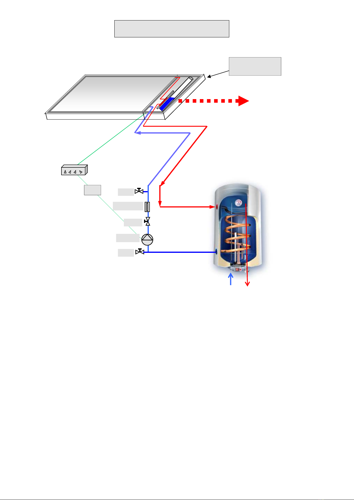
1.1 The S 30AWX Principle
Flow meter
Hot water cylinder supplying
100 l domestic hot water
S 30AWX solar collector
12 v solar cells for
fan and pump
Cold water in Hot water out
Warm air into
the house
12V Pump
Valve
Valve
Valve
12 v
Regulator
5
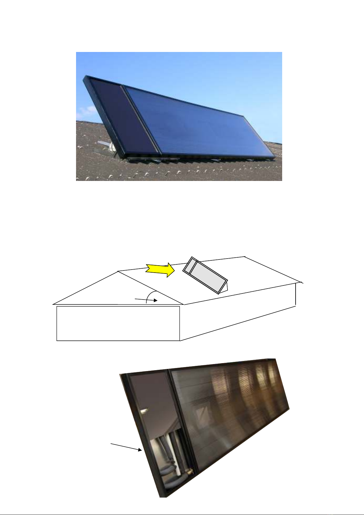
Please note that the S 30AWX solar collector is located with the long dimension
parallel to the horizontal - or the side with the solar cell at the highest position.
Inlet and outlet are always placed on the same side of the collector. By rotating
the collector 180º you may choose between the right and the left side.
1.2 A roof mo nted SV30AWX solar collector
Max 45 degrees
5
Tubing and expansion unit is
placed behind the solar cell

6
2.0
Planning the position of the SV30AWX
This low-tech plant is designed to let the forces of nature work for you to the maximum practical extent. This
will benefit the environment and reduce your costs of living for many years ahead.
In order to ensure the optimal performance of your S 30AWX it is important to consider:-
• The position of the solar collector in relation to the sun and to the rooms of the house
• The position of the other components in relation to the collector and the construction of the house
• The interaction between the various parts of the system
The instructions given below will take you through this process step by step
2.1 How to position the SV30AWX solar collector
• In relation to the s n:
When planning the position of the collector on roof or wall you will have to consider how the maximum
amount of sunlight can be received. If possible the collector should be directed at solar noon. However,
a deviation of up to 45º is acceptable. The inclination from horizontal should range between 30º and
60º. App. 45º is optimal.
• In relation to the rooms of the ho se:
Please note that the incoming fresh, warm air can only be achieved with the inlet vent in the immediate
vicinity of the collector, so it is important to place the collector above (or against) a room well suited for
this purpose.
Please read separate instr ctions for f rther details.
2.2 How to position the hot water cylinder
The hot water cylinder should be installed so that the horizontal distance to the S 30AWX solar collector is
as short as possible.
The hot water cylinder can often be located in a scullery or a furnace room or wherever practical. However,
there must be access to both power and the domestic water s pply.
The location should incl de a drain as water will occasionally drip from a safety valve.
An open space of 50 cm minimum should be maintained in front of the cylinder for service access.
If possible, ensure that additional space is reserved for service of the equipment below the bottom of the cyl-
inder too. In case of restricted space, a safety valve may be placed on the side of the cylinder.
Space must be reserved for piping to and from the S 30AWX solar collector. Lead-in is often made through
ceiling and floor. Please note that all piping to and from the collector must be insulated.
If the hot water cylinder is located in a loft, a frost-proof outlet must be established. Use anti-freeze to avoid
potential frost in the pipes. If an electric water heater is used for frost protection a thermostat should be in-
stalled to prevent it from working when the room temperature exceeds +5ºC.
Take care not to impair or damage the fabric of the b ilding when installing the hot water cylinder.

7
2.3 Concerning piping location
Horizontal or ascending piping from the hot water cylinder to the S 30AWX solar collector is optimal. Otherwise you
may have problems starting the installation.
It is possible to place the expansion tank below collector level. However, the difference in height between the top of
the collector and the bottom of the expansion tank should be a maximum of 2 m.
Care should be taken to avoid bends (no air pockets!) and to establish either a horizontal or a falling piping run be-
tween the expansion tank and the cylinder as the pump pressure is released behind the expansion tank.
S
olarVenti
SV30AWX system principal drawing
(Patented air and fluid collector) HJC June. 2011
Patented collector:
Europe: EP 1448937 Incl. Eurasia
Japan: 3808466
China; 02823485.5
Australia: 2002350429
USA: US 7,694,672 B2
Canada: 2,467,078
3000 mm
1020
Area 1 for copper absorber
Udgang fra
absorber
A
A
iew from above
(without PC cover)
Air outlet
Backside of the collector
Perforereted plate for air inlet
C
Luft opvarmes i hele solfangeren
area for solar air absorber
æske indløb
for absorber
Se description
on page 9
o
460 mm
Connect all tubing
and place the solar
cell on top
Area 2 for copper absorber

8
3.0 Installation Instr ctions
3.1 Installing the SV30AWX Solar Collector
Please follow the general installation instructions for the S 30. These instructions come in three versions which are
all included:
S 30AX on roof type 1 (fibre cement, tile etc. Type of roof with overlapping plates or similar)
S 30AX on roof type 2 (asphalt or steel plates. Type of roof with no overlapping)
If placed on the wall the S 30AWX should have an angel of 40 - 60 degrees from horizontal (the smaller angel the
more warm water in summer - and less warm air in winter)
3.1.1 Drilling holes in the roof
One hole Ø = 20 mm is made for the cold piping to the S 30AWX solar collector. This hole is made next to the lowest
pipe outlet on the collector. (For type 1, take care always to drill in crests!)
A second hole Ø = 20 mm for the hot piping from the collector is made next to the first. (See page 7)
Before drilling make sure that the position is correct.
A rubber lead-in will secure the watertight lead-in of the 16 mm tube through the roof plate.
3.2 Piping and Ins lation
1) 16 mm tube (smooth tube for distances over 12 m) is insulated and fixed. Fasten the tubes with strips or wire
to laths at short invervals to avoid bends.
2) Intense heating may result in linear expansion especially in rib tubes, but smooth tubes will also expand to
some degree. Normally, this causes no problems. However, care should be taken to prevent the pipes from
rubbing on sharp edges or the like.
.
Long piping arrangement on the roof
If it is necessary to lay tubes outside on a roof etc., the insulation must be protected by a wind and weather proof
tube. This kind of tube comes in 25, 39, 48 and 63 mm Ø and can be pulled over the insulation.
Note: The wire on the roof is sec red from birds by p lling it thro gh the rib t be
3.3 Roof lead-in
Roof penetration
The rubber let in is put directly in a 19-20 mm hole in the
top of the roof. The 16 mm tube may be pulled through
this. Use some soap so that it will slide through.
25 mm rib tube or
insolation protects
the 16 mm tube
16 mm PP tube
top of roof plate
with 19-20 mm hole
Rubber let in

9
Notice!
If the expansion tank is filled above
the recommended level a loss of
heat may incur as a result of the self
circulation, and the space reserved
for fluid expansion will be reduced
3.4 Installing the expansion tank
Expansion Tank
Hot fluid from the
solar collector
Hot fluid to the hot water
cylinder.
The following tubing must
be placed underneath the
minimum level of fluid.
Cold fluid from the
hot water cylinder
Air inlet and outleton top
of expansion tank
ormal level of fluid.
Max level of fluid.
Minimum level of fluid.
Be caref ll not to overfill the tank
extra fluid may be filled in here
Clear tube to control fluid level. Hide under
the collector when not in use. Put a lid on top
of this tube (with a tiny hole for the air)
The expansion unit has several purposes:
1) to absorb the expansion of the fluid when hot
2) To let out the air from the fluid
3) can contain all fluid of the collector if it should
boil
4) this protects the fluid from being damaged
5) needs no maintenance
6) runs without pressure

10
3.5 Installing the hot water cylinder
Important: The base or wall fittings m st be dimensioned to carry a f ll cylinder (app 150 kg)
3.5.1 Fittings on the hot water cylinder
The hot water cylinder is supplied with a range of connecting parts and a pump. Please follow the direc
tions for fitting these items. More details are on the next pages.
The hot water cylinder m st be connected to a
safety valve which will let excess pressure out of
the cylinder. Water will drip from the safety valve
when the temperature rises in the cylinder due to the
expansion of hot water. Therefore, it must be con-
nected to a drain.
Important: Note the marking for flow direction on the p mp and be
s re to fit it in a vertical position so that it can self ventilate!
Hot supply
line
To the bottom of
the solar collector
12 V pump with
5 speed steps
Piping with 16 mm
PP tubes
Expansion tank
Flow meter
Tube stubs are fitted to
2 and 3 for filling and
starting aid
Cold domestic water inlet
Pre-heated water out
Pre-installed
or new electric
water heater
Exist. safety valve
V2
V3
V4
V1
Air outlet
Hose nippel may be
put on V2 and V3 for
filling and start up.
A trab prevents pre-
vents the release of
heat
safety valve
Table des matières


