Solar Boiler SB32-9PV Manuel utilisateur
S E N S I B L E
E C O L O G I C A L
E C O N O M I C A L
A F F O R D A B L E
S E N S I B L E
E C O L O G I C A L
E C O N O M I C A L
A F F O R D A B L E
S E N S I B L E
E C O L O G I C A L
E C O N O M I C A L
A F F O R D A B L E
S E N S I B L E
E C O L O G I C A L
E C O N O M I C A L
A F F O R D A B L E
S E N S I B L E
E C O L O G I C A L
E C O N O M I C A L
A F F O R D A B L E
S E N S I B L E
E C O L O G I C A L
E C O N O M I C A L
A F F O R D A B L E
S E N S I B L E
Solar Boiler
TM
INSTALLATION MANUAL FOR MODELS:
SB32-9PV AND SB64-9PV
WARNING
The approved heat transfer uid is 40% Propylene Glycol USP and 60% distilled
water. The substituion of any other heat transfer uid can cause irreparable dam-
age and create a health and safety hazard.
The Solar Boiler™ module conatins 3.75 liters (1 US gallon) of heat transfer uid
when full.
The installation of the Solar Boiler™ system should be installed by a qualied
technician.
Assemblies and materials shall meet requirements of the applicable codes and
Standards for re safety.
Solar Boiler™
Congratulations on the purchase on your new Solar Boiler™ system by Thermo
Dynamics Ltd. The Solar Boiler™ is the newest and most advanced concept in
residential solar domestic water heating systems.
This manual outlines all of the steps necessary for a quick trouble free installation.
Read the entire manual carefully before any installation attempt is made.
Be sure to follow all local codes when installing the Solar boiler system.
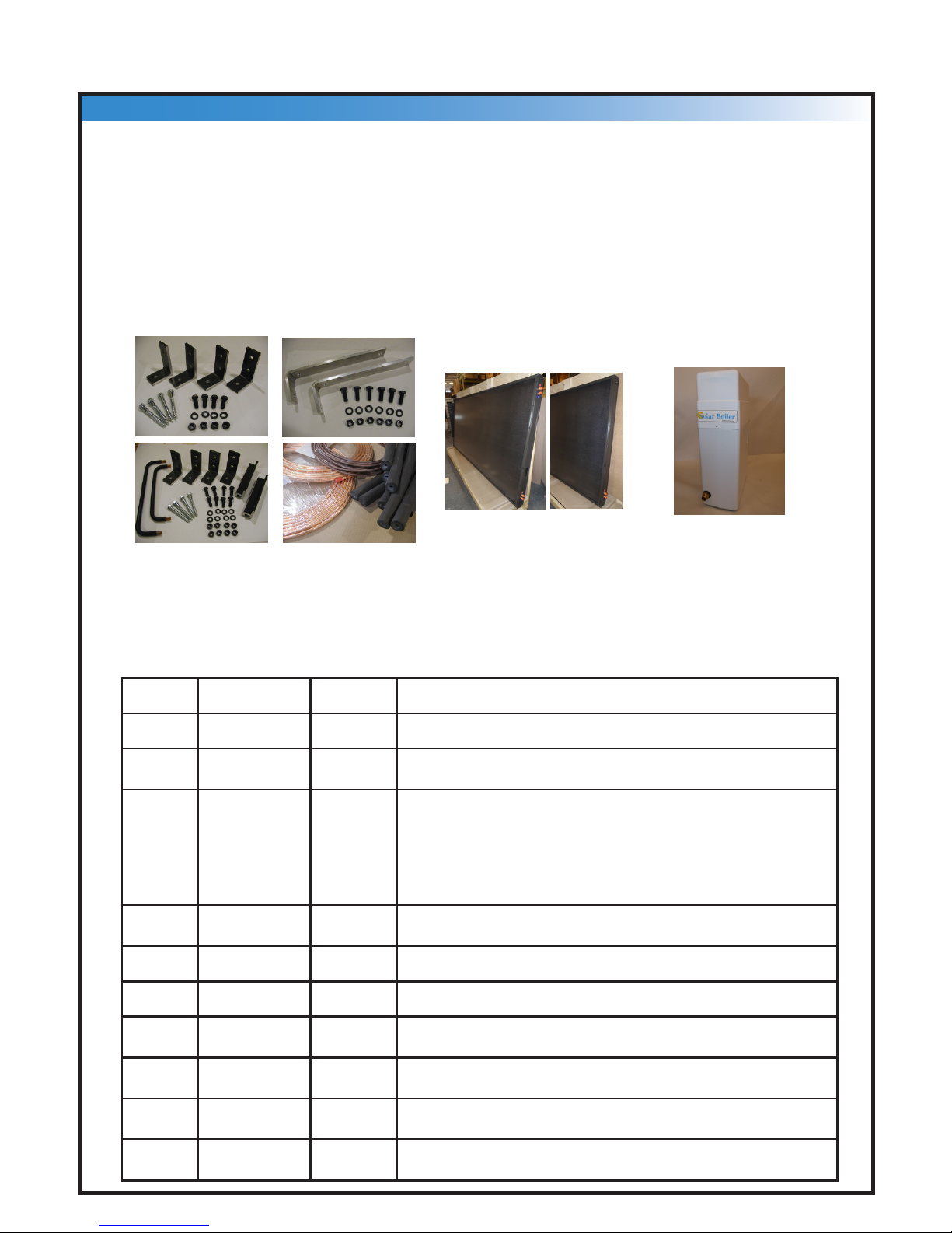
Quantity System Model Description
1 SB64-9PV only S32A-P 4’ x 8’ S Series Serpenitne Collector, “A”, 4 ports
1 SB32-9PV
SB64-9PV
S32B-P 4’ x 8’ S Series Serpentine Collector, “B”, 2 ports
1 SB32-9PV
SB64-9PV
SBM13DC Solar Boiler Module
- Solar Pump (complete with Delta-T Booster II and temp sensors)
- Heat Exchanger
- Expansion Tank
- Glycol Resevoir (Complete with 4 liters of glycol)
- Glycol inlet/outlet ports
- Water inlet/outlet ports
1 SB32-9PV
SB64-9PV
PV20 Photovoltaic Module, 20 Watt
1 SB32-9PV only K1050 Serpentine Collector Mounting Kit (for 1 S Series - mounts ush to roof)
1 SB64 9PV only K1055 Serpentine Collector Mounting Kit (for 2 S Series - mounts ush to roof)
1 SB32-9PV
SB64-9PV
K1060 Photovoltaic mounting kit (mounts to Serpentine Collector)
1 SB32-9PV
SB64-9PV
K2030-50 Copper Tube Kit (3/8” Copper tube, 2 x 50 ft, Insulation, 100 ft, 18/4 LVT
wire, 60 ft
1 SB32-9PV
SB64-9PV
GLYUSM Propylene Glcyol USP, (mixed 40% glycol 60% water), 4 liters
1 SB32-9PV
SB64-9PV
Tank Connection Fittings, (Brass)
SB32-9PV and SB64-9PV Solar Boiler™ System Components
K1050
K2030-50K1055
K1060
1
A 270 liter, (60 IG) Storage tank is required for the installation and is not included.
In Canada, the tank must be CSA approved and all plumbing ttings must comply
with CSA B.125
S32A S32B
Solar Collectors
S Series (Micro-Flo®)
Solar Boiler™ module
Installation Manual for SB32-9PV and SB64-9PV
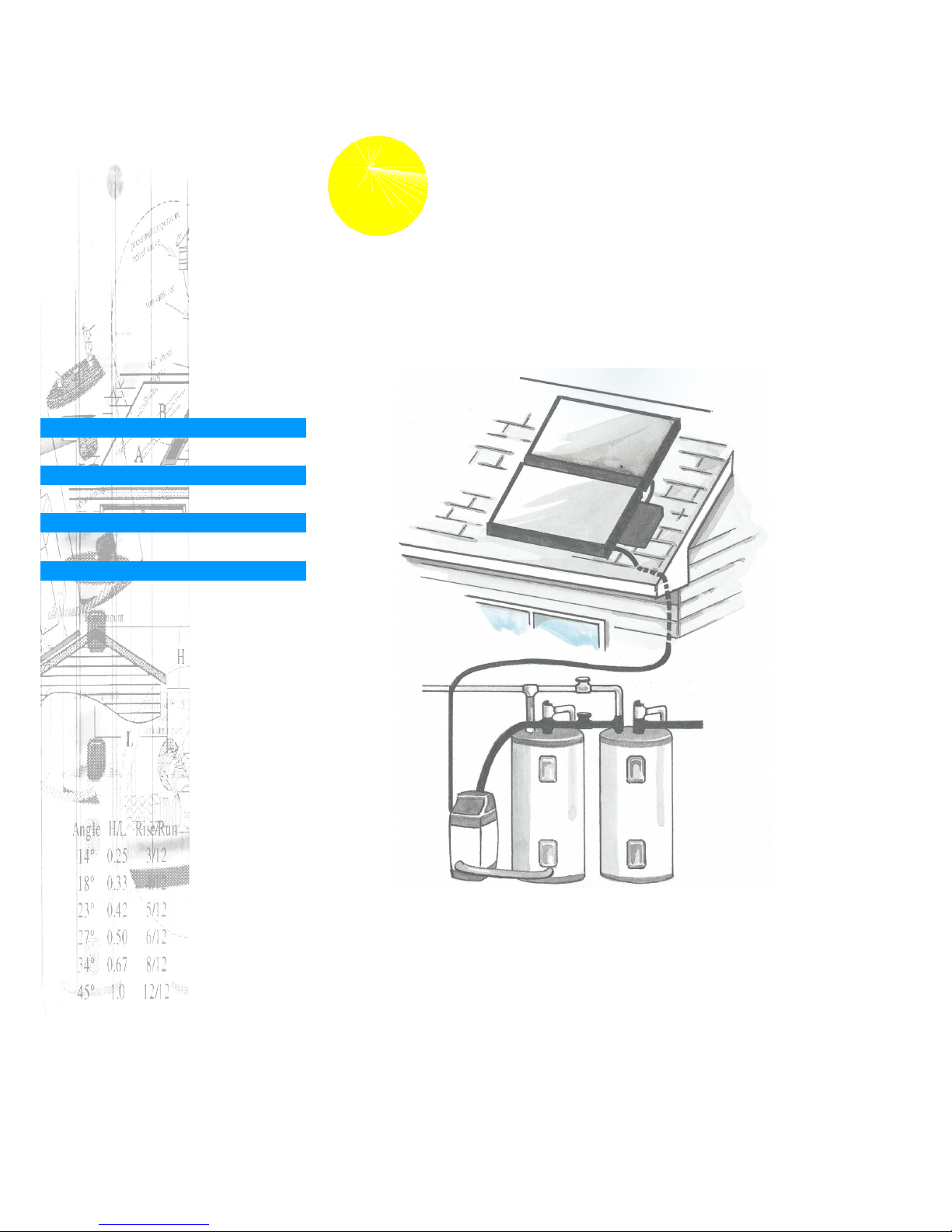
• Solar collectors absorb sunlight and convert it to heat.
• When there is sufcient sunlight, the photovoltaic module pro-
duces electricity and turns the pump.
• The pump circulates heat transfer uid, (HTF), through the
solar collectors.
• Heat is transferred to the HTF in
the solar collector.
• The HTF is returned to the heat
exchanger in the Solar Boiler™
module.
• The heat is transferred to the wa-
ter which circulates naturally to the
top of the solar storage tank.
• Solar heated water is stored in the
solar storage tank until water is
drawn from the auxiliary tank (in
this case an electric water heater).
• As hot water is drawn from the
electric water heater it is replaced
with solar heated water.
• The electric heaters increase the
temperature of the solar heated
water, if necessary.
• The electrical energy required
to heat water is signicantly less
when water is preheated by the
solar water heater.
• In this manner, the solar water heater saves electrical energy.
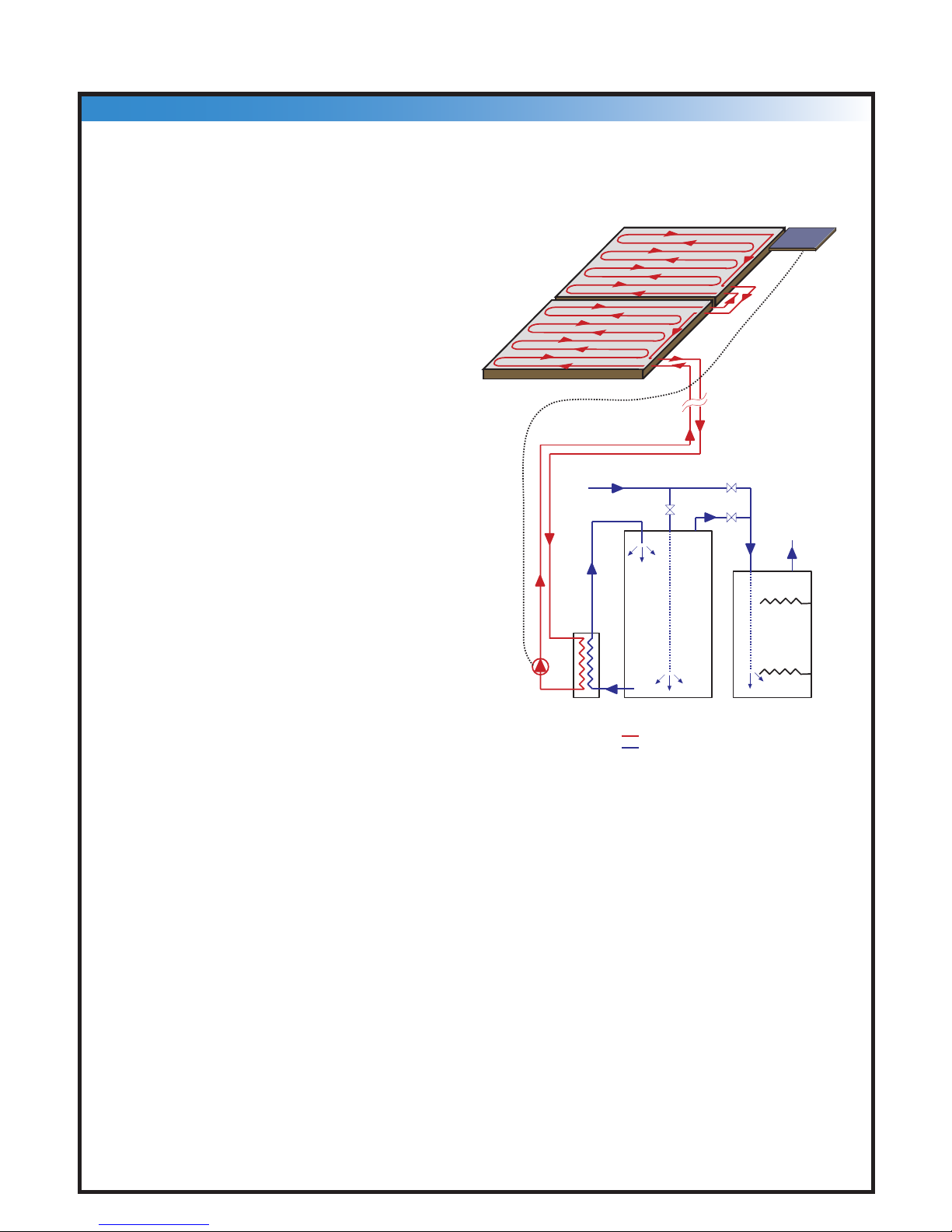
S32 A
Solar Collector
[Optional]
S32B
Solar Collector PV module
Wire - supplies 12 VDC
from PV module to
Solar Boiler™
Cold Water IN
Hot Water OUT
Solar Storage Tank Auxiliary Water Heater
Solar Boiler™
module
Solar Pump™
Ball valve #1
Ball valve #3
Ball valve #2
Normal Operation
Ball valve #1 - Close
Ball valve #2 - Open
Ball valve #3 - Open
[Inside the Solar
Boiler™]
solar heated water IN
cold water IN
solar heated water IN
HTF [heat transfer fluid]
Domestic Water
How the Solar Boiler™ Works
NOTE:
The Solar Boiler™ is designed to shut off when a temperature of 70°C (158°F) is at-
tained in the solar storage tank.
The heat transfer uid is a 40/60 % by volume mixture of Propylene Glycol USP and
distilled water. The Solar Boiler™ module contains 3.75 liters (1 US gallon) of heat
transfer uid. An additional 3.75 liters (1 US gallon) is supplied with the system for
lling the system during start up.
The maximum safe working pressure of the heat transfer uid is 60 psi, (410 kPa).
The Solar Boiler™ system is inherently grounded through copper piping connected
to the main water supply. Ensure that household ground is adequately electrically
grounded.
2
Solar Boiler™
System and Installer Details
Installer
Address
Tel:
Fax
Email:
System Details
Solar Boiler Model
Solar Collector Serial#(s)
Solar Boiler Serial#
Storage Tank Serial#
Orientation E or W of South
Collector Slope
Collector Mount (Flush or Inclined)
3
Installation Manual for SB32-9PV and SB64-9PV
S o ut h
A
B
Inclined mount
H
L
Flush mount
South
H/L
0.25
0.33
0.42
0.50
0.67
1.0
Angle
14°
18°
23°
27°
34°
45°
Rise/Run
3/12
4/12
5/12
6/12
8/12
12/12
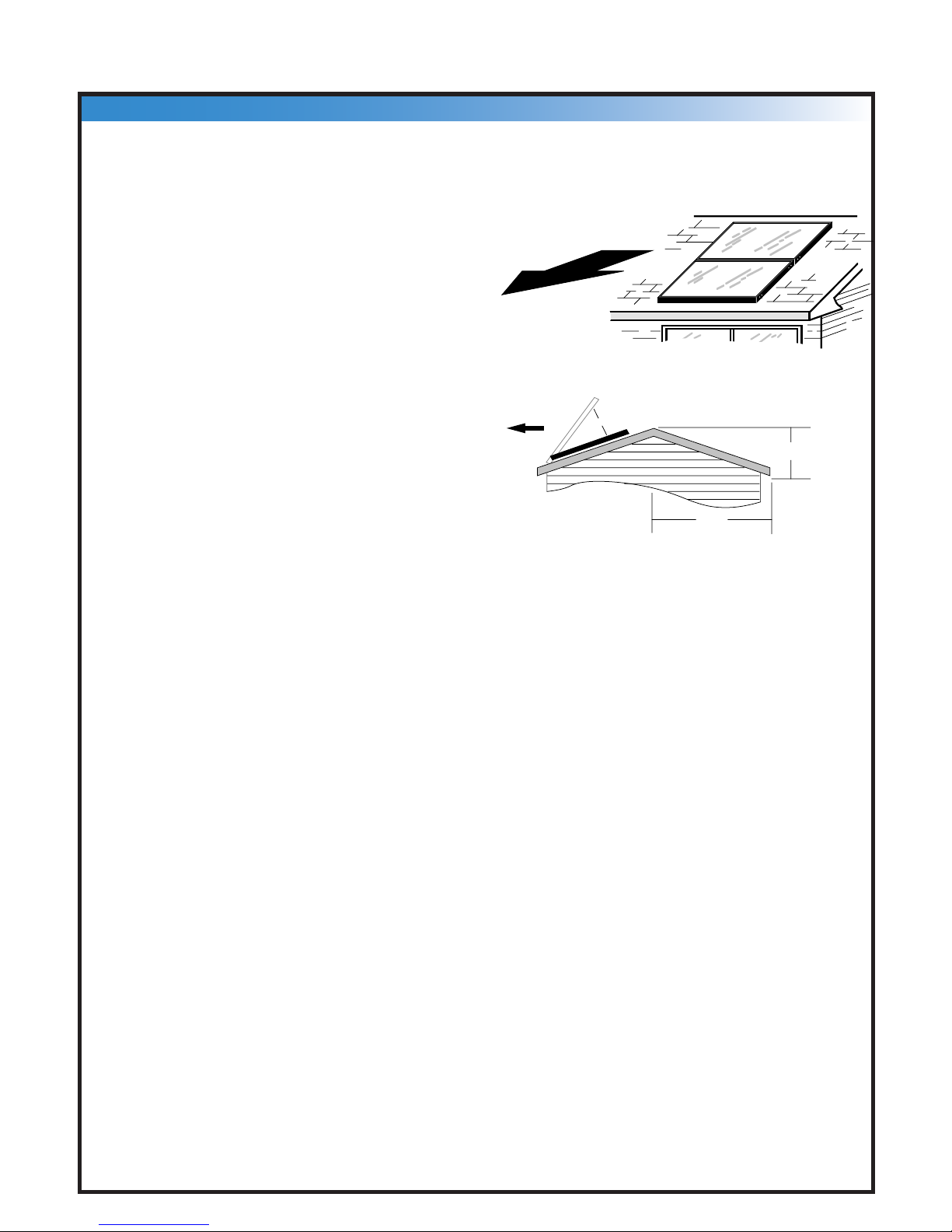
Micro-Flo® solar collectors are de-
signed to work with the Solar Boiler™
module and other Micro-Flo® systems.
Locate the solar collectors on the roof
of your home that is oriented true south
or as close as possible. There are no
major losses up to 45° east or west of
true south. If your orientation is not in
this range, consider a ground mounting
system. The solar collectors are to be
installed such that they are not shaded
for at least 5-6 hours during the middle
of the day.
The recommended slope is equal to the
local latitude plus or minus 10°. For
example, Halifax, Nova Scotia is at a
latitude of 45°. Therefore the recom-
mended collector slope for a home lo-
cated in or near Halifax is between 35°
and 55°. For effective snow removal
in the winter a slope of at least 45° is
recommended.
To calculate the slope of your roof,
measure the dimensions “H” and “L”
as shown in the gure. Calculate the
quantity H/L and compare it to the table
to determine if an inclined mount is
required.
Inclined Mount
The inclined mounting kit allows the
collectors to pivot in the front and uses
aluminum channel to support the solar
collector at the rear. Instructions are
provided with the rack mount kit.
Solar Collector Location
4
Solar Boiler™
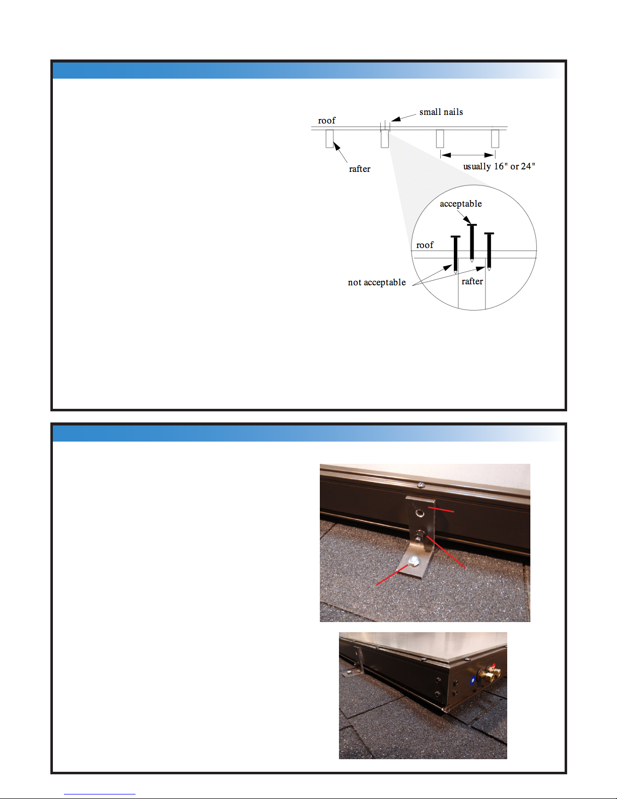
Locate the rafters directly under the
solar collectors, and at least 8” from
the ends of the solar collectors. In
the case of 4’ x 8’ solar collectors and
24” rafter spacing, the clips should be
mounted six feet apart (that is, one
foot from the edge of the collector).
To nd the center of the rafters, lift the
shingle and use small nails to nd the
two edges of the rafter.
Drill a 1/4” pilot hole in the rafter for
each of the front mounting clips.
Fill the holes with silicon sealant and
secure the two front clips to the roof
using lag bolts. Seal the perimeter of
each mounting clip base with silicon.
Take the “A” solar collector and slide
two 3/8” bolts in the bolt track.
Loosely fasten these bolts to the bot-
tom hole of the front mounting clips
using a lock washer and nut.
Center the solar collector so that the
spacing from the end of the solar col-
lector to the mounting clip is equal on
both ends. The solar collector ports
must be on the right hand corner of
the solar collector when, viewed from
below.
1 – Locating Roof Rafters
2 – Flush Mounting Micro-Flo® Solar Collectors
5
3/8” Bolt,
nut, lock
washer
3/8” lag
screw
Mounting Clip
Installation Manual for SB32-9PV and SB64-9PV
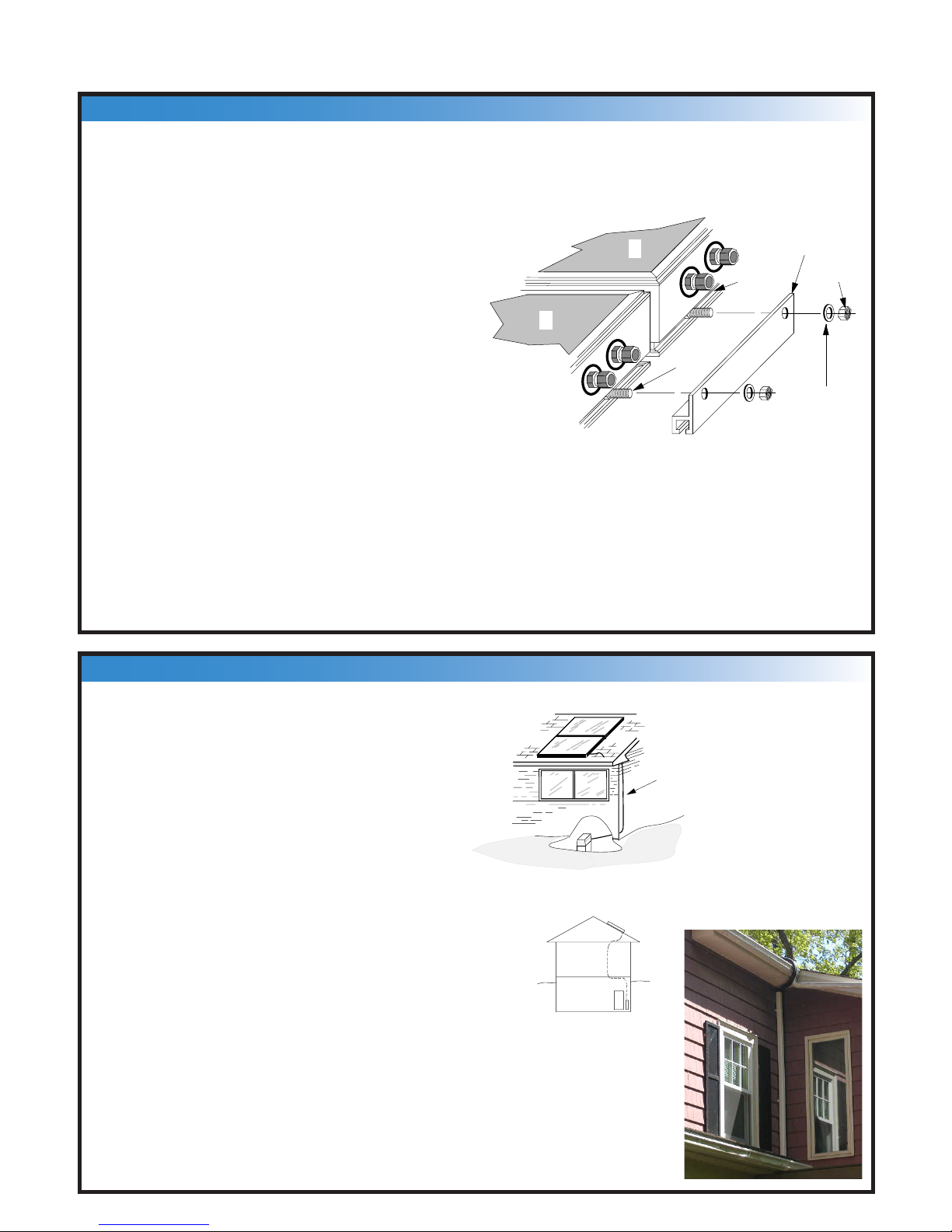
If you have a two solar collector system,
place the B solar collector above the A
solar collector. Make sure that the ports
are on the right hand side.
Using the aluminum channel, fasten col-
lector B to A as shown in the gure.
Fasten the upper mounting clips (not
shown) to the top of the collector(s),
and use lag bolts to secure them to the
rafters in the same manner as for solar
collector A.
Tighten all nuts that secure the
collector(s) to the mounting clips.
Silicon seal all roof attachments.
lock
washer
bolt track
3/8" bolt
aluminum
channel, (6")
3/8" nut
A
B
IN
IN
OUT
OUT
3 – Optional Second Solar Collector
4 – Copper Tube Kit Installation
LifeLine® tubin g
A
B
The copper tube kit is used to connect
the Solar Boiler™ module to the solar
collectors.
All of the copper tubing should be
sleeved with the insulation provided.
The insulation is Elastomeric Expanded
Closed Cell with a 0.5” thickness. Mark
one copper tube at both ends with tape
to identify the supply and return lines.
Run the copper tube and PV Sensor
wire (LVT 18/4) to the solar collectors
via an unused space or closet. If the
bundle is run outside along the house, sleeve it in a plastic
conduit such as down spout. Note: All copper tube installed
in the horizontal position must slope down 1/4" for every hori-
zontal foot. Secure the Copper tube at intervals of 6 feet with
clamps. Use caution when bending the tube to avoid kinking.
6
Solar Boiler™
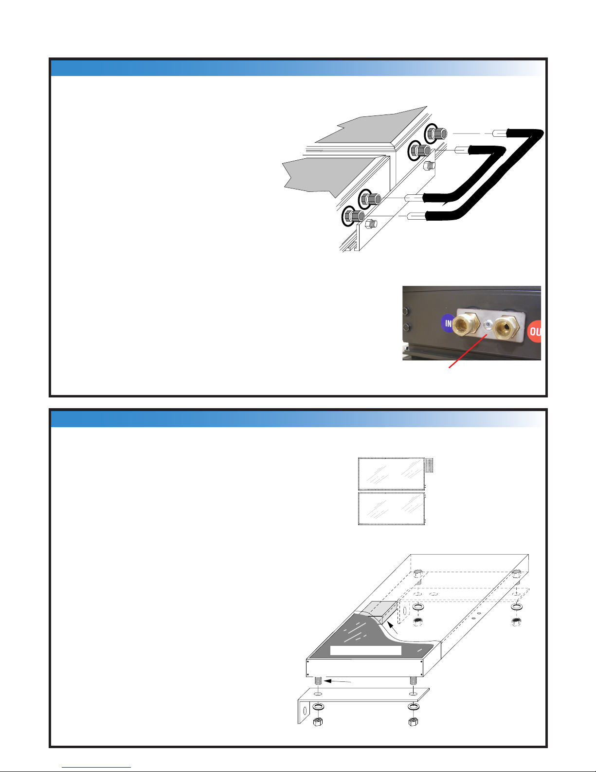
5 – Copper Tube at Solar Collectors
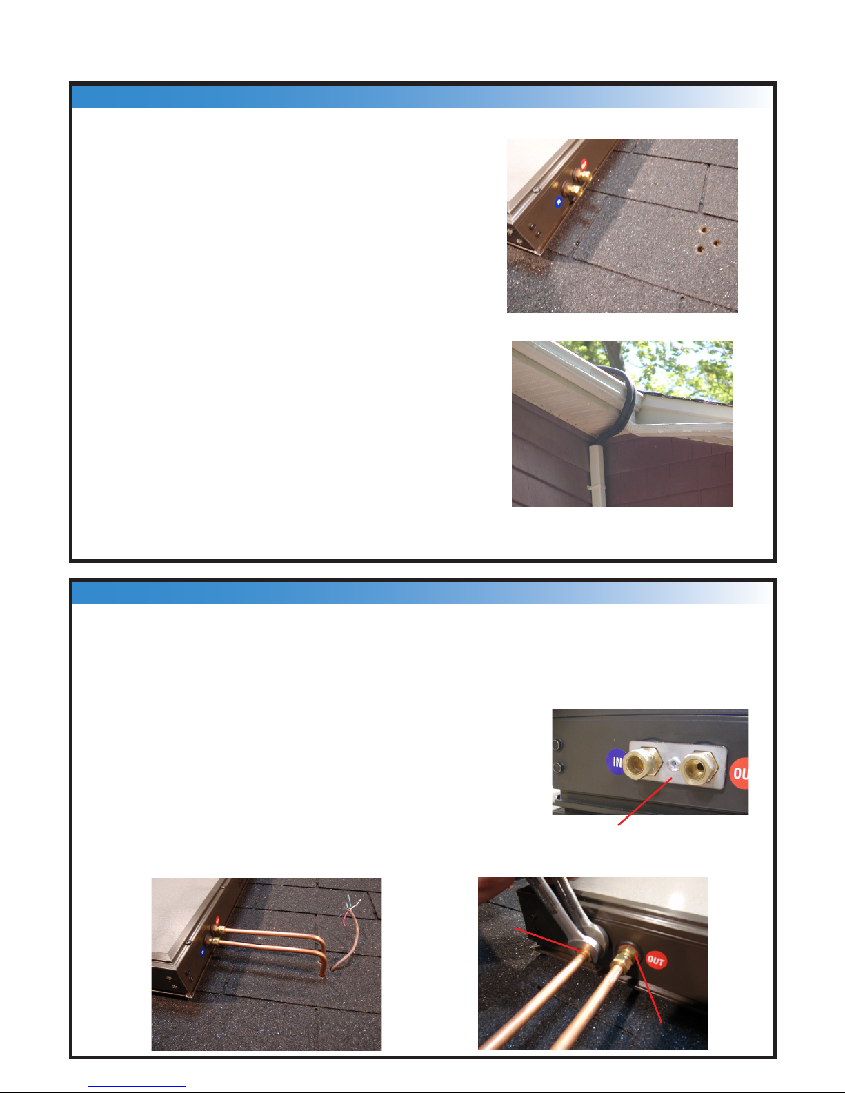
The copper tube roof penetration is made adjacent
to the “A” collector for the SB64-9PV system and
the “B” collector for a SB32-9PV system.
Make a roof penetration at a position 8" - 10" hori-
zontally away from the “A”, (“B”) collector bottom
ports. A 3/8” hole for each tube and the wire is
sufcient.
Pass about 2 feet of Copper tube through the roof
penetration from below. Clamp the copper tube to
the truss. Do not crimp the copper tube.
Seal the roof penetration with silicon sealant.
If the copper tube has been installed on the outside
of the house, a roof penetration is not necessary.
Simply bend the tubing bundle around the soft
and up to the solar collectors
Connect the 3/8" copper tube to the "IN" (blue) port using a 5/8" and 11/16”
wrench. Be sure to hold the bulkhead union from moving during this process.
Connect the other 3/8" copper tube to the "OUT" (red) port.
6 – Copper Tube Connection to Collector
7
Bulkhead Union
3/8” Compression
Nut
IMPORTANT: The 11/16” wrench is required to pre-
vent the bulkhead union from rotating while turning
the nut with the 5/8” wrench.
As of January 2010, S Series collectors are
equipped with Bulkhead Union locking plates. This
eliminates the need for an 11/16” wrench. Bulkhead Union Locking Plate
Installation Manual for SB32-9PV and SB64-9PV
Place the 3/8" compression nuts
on the tting body nger tight.
Insert the copper tubes into the
ports as shown, until they bottom
out.
Using a 5/8" and a 11/16" wrench,
tighten the nuts one full turn.
IMPORTANT: The 11/16" wrench is required to prevent the
tting body from rotating while turning the nut with the 5/8"
wrench.
As of January 2010, S Series collectors are equipped with
Bulkhead Union locking plates. This eliminates the need
for an 11/16” wrench.
IN
OUT
IN
OUT
Attach the two large aluminum brackets
to the photovoltaic module using the
3/8" bolts, nuts, and lock washers sup-
plied. Make sure that the junction box on
the back of the PV panel is at the top.
Make sure both aluminum angle brackets
are securely fastened to the photovoltaic
module.
Grounding: The photovoltaic module is
inherently grounded through the mount-
ing hardware attached to the solar collec-
tors.
A
B
PV
3/8" nut and
lock washer
3/8"
bolt
Photovoltaic module
junction box
8 – Preparing the Photovoltaic Module
7 – Connection Between Collector A and B
8
Bulkhead Union Locking Plate
Solar Boiler™
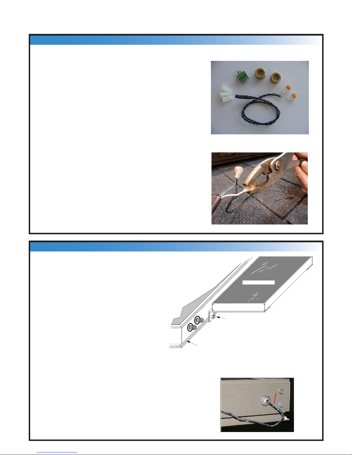
Open the junction box located on the photo-
volatic module, and note the positive terminal
marked "+" and the negative terminal marked
"-".
Drill 2 small holes and insert the 18/4 LVT wire
in the box. Connect the “RED” to “+” terminal
and the “BLACK” to “-” terminal.
If your “B” solar collector is equipped with a
sensor enclosure as pictured in step 10a, pro-
ceed to step 10a.
Feed the white and green wires out of the
junction box and connect them to the collector
sensor using pinch connectors supplied.
Locate the photovoltaic module as
shown in the diagram, along the port
side of the “B” collector. Using the
3/8" bolts, washer, and nuts, attach
the photovoltaic module to the "B"
collector bolt track as shown in the
diagram. Ensure that all the nuts
are tightened securely in order to
provide proper grounding of the PV
module.
Insert the temperature sensor into
the “B” collector. It should go in
about 6 to 8 inches. Seal with
silicon.
Using the connectors provided,
crimp the sensor wires to the green
and white wires.
Photovoltaic module
"B"
Collector
bolt
track
3/8" bolt, washer,
nut
9 – Wiring the Photovoltaic Module and Collector Sensor
10 – Locating the Photovoltaic Module
9
Temperature Sensor
Compression Nuts
Service Plug
Collector Temperature Sensor
Pinch
Connectors
Dart Clips
PV/Sensor wire
Ce manuel convient aux modèles suivants
1
Table des matières
Manuels Chaudière populaires d'autres marques

Vaillant
Vaillant uniSTOR VIH SW GB 500 BES Manuel utilisateur

Radijator
Radijator BIO max 23.1 Manuel utilisateur

Brunner
Brunner BSV 20 Manuel utilisateur

Buderus
Buderus Logamax GB062-24 KDE H V2 Manuel utilisateur

Potterton
Potterton 50e Fiche technique

UTICA BOILERS
UTICA BOILERS TriFire Manuel utilisateur


