SmartLine SL1600 Manuel utilisateur
• Align the three retainers on back of the controller housing onto the
mounting bracket and lower it into place.
• For additional security, install a bottom cen-
ter mounting screw from the inside of the
controller. Drive the provided screw through
the mounting notch located just below the
zone modules to secure the controller to the
bracket.
2B. Installing Without Quick Mount Bracket
• Determine mounting height for easy viewing and be sure to mount low
enough for field wires to reach controller wiring terminals and test post
at top of controller.
• Install a wall anchor in the desired location.
This will be for the top/center hanger hole of
the controller.
• Install one of the mounting screws provided
into the wall anchor.
Hang the controller on the mounting screw by
positioning the controller on the head of the
mounting screw. Check the controller for level,
then drive a 2nd screw into the “notch” inside
the bottom/center location to mark position for second anchor. Remove
controller from top keyhole and install second anchor and then remount
controller and tighten both screws to secure unit.
3. SLM4 Module Installation
• The SL1600 controller is equipped with one 4-zone module (SLM4).
Additional SLM4 modules may be added to expand capacity to 16
zones. The SL1620 has 20 fixed zones; the SL1624 has 24 fixed zones.
The SLM4 module is useable only on the SL1600.
• The SL1600 controller will automatically recog-
nize the additional zones as they are installed.
No special programming or resetting is
required to initialize the modules.
• You can insert or remove a module without
removing power from the controller.
• To install a module, push the module into
the channels until you feel it lock in place. To
remove a module, push DOWN on the center release panel on the top
of the module and use the top tab to pull it out.
4. AC Power Wiring
• Plug the included 6-foot line cord into a 120VAC outlet. (E-SL1600
units for international use are prewired for 230VAC.)
• Do NOT use a switch controlled wall outlet for operating an irrigation
controller.
TEST
AC1
SEN
SEN
COM
P/MV
RED
BLACK
SILVER
Note: Modules must be inserted in the sequence of numbered
zones. Do not leave any gaps in module positions.
TEST
AC1
SEN
SEN
COM
P/MV
RED
BLACK
SILVER
1. Controller Installation
All SL1600 controller housings are designed for indoor or outdoor instal-
lation. Your SL1600 controller can be located in any convenient spot such
as inside the garage or on an outside wall. It is recommended that you
choose a location where the irrigation system will not be spraying directly
on the controller, in the event the housing door is left open.
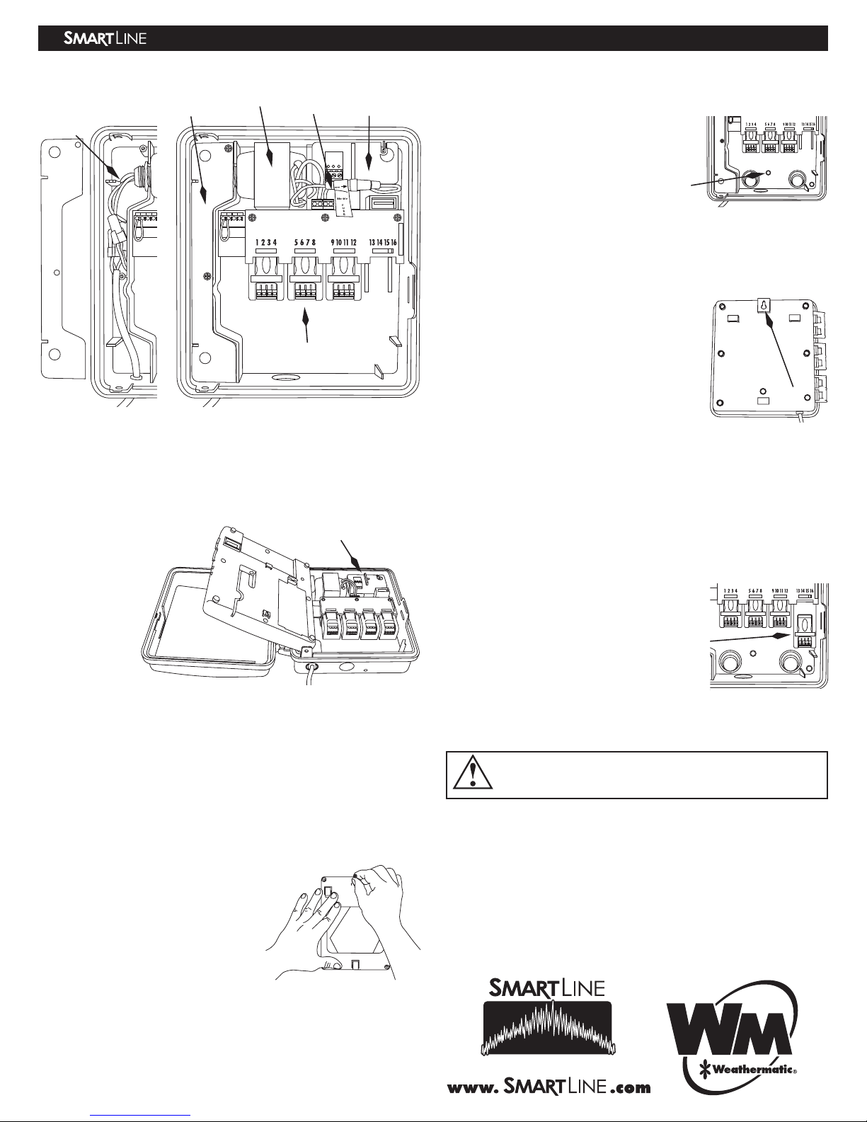
• Open the
controller’s
front door,
then open the
control panel
of your SL1600
controller.
• Remove the
control panel
from the
SL1600 con-
troller housing
by pushing
upward and outward to remove from the hinges, then set the control
panel aside in a safe place.
• Mount the SL1600 controller with or without the SL1600 controller Quick
Mount bracket.
2A. Installing With Quick Mount Bracket (recommended)
• Determine mounting height for easy viewing and be sure to mount low
enough for field wires to reach all controller wiring terminals and test
post at top of controller.
• Place the mounting bracket against the
wall so that the word “CONTROLLER
SIDE” is visible and the open ends of the
housing retainers are pointing upward.
• Using one of the mounting screws (or a
pencil) mark the location onto the wall of
the top/center hole (see photo).
• Install a wall anchor in the marked
position then install the bracket onto
the anchor using one of the mounting screws provided (do not tighten
screw fully yet). The center screw will automatically level the bracket on
the wall. After level is set, mark the other mounting holes and install the
remaining wall anchors.
• Install other screws through bracket into anchors (except for bottom cen-
ter screw) and tighten all screws.
TEST
AC1
SEN
SEN
COM
MV/P
RED
BLACK
SILVER
TEST
AC1
SEN
SEN
COM
MV/P
RED
BLACK
SILVER
A
C Wiring Cavity
with panel removed
MOV (Metal
Oxide Varistor)
Installed SLM4 Modules
AC Wiring
Cavity panel
Optional SLHUB
Communication Hub
Transformer Test
Post
SL1600 Interior Layout
SL1600 Controller Installation Instructions
®
Optional
SLHUB
CONTROLL
THIS
™
Alternate Wiring
If you are mounting your SL1600 controller outdoors or local electrical
codes require hard wiring, proceed with the following steps.
Warning: Connecting the SL1600 controller to the primary power
should be done by a licensed electrician following all local codes.
To prevent electrical shock, make sure all supply power is turned
OFF at the breaker before connecting these wires. Electrical shock
can cause severe injury or death. This controller is not intended for
use by children. Do not allow children to play with the controller.
• Remove the screws that secure the AC Wiring Cavity Panel. This will
allow access to the transformer wiring.
• Disconnect the existing line cord connected to the transformer wires.
• For use with conduit, simply remove the line cord knockout. To do this,
use a small, flat screwdriver blade in the slot of the knockout on the
underside of the controller housing. Tap out the knockout with a ham-
mer. Install the conduit and wiring. Discard the line cord.
• For 120VAC operation, using wire nuts, make the wire connections indi-
cated in the chart below.
• For 230VAC operation, using wire nuts, make the wire connections indi-
cated in the chart below.
• Replace the AC Wire Cavity Panel and secure with the screws.
• Return to the breaker box and turn on the circuit breaker. Verify that
the controller no longer displays “no AC.” This indicates that the AC
power is on.
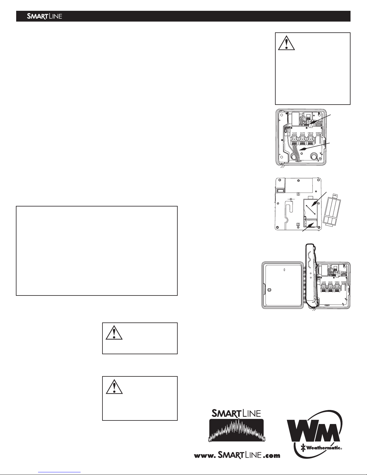
5. 24VAC Valve Wiring
WARNING: Never mix 24VAC and high voltage wiring in the same
conduit.
• For solid wires, simply push to
insert the stripped end of valve wire
into the module connector.
• For stranded wires, use a small
screwdriver blade to push back the
orange slide lock trigger first, then insert the stranded wire while holding
the trigger in the open position. When you release the orange slide trig-
ger, the wire will lock in place.
• Knockouts: The SL1600 controller
provides several convenient knock-
outs for your choice of routing for
valve and accessory 24VAC wiring.
The knockouts should be removed
by striking with a hammer and
screwdriver inwards, toward the
inside of the housing.
•
COM (Valve Common): Connect the Valve Common wire to the COM ter-
minal.
Wire connections TRANSFORMER
for 120VAC WIRE COLOR AC INPUT WIRE NOTE
BLACK NEUTRAL
WHITE 120VAC HOT
RED DO NOT USE-230VAC (cover with wire nut)
GREEN/
YELLOW EARTH GROUND (typically green wire)
Wire connections TRANSFORMER
for 230VAC WIRE COLOR AC INPUT WIRE NOTE
BLACK NEUTRAL
WHITE DO NOT USE-120VAC (cover with wire nut)
RED 230VAC HOT
GREEN/
YELLOW EARTH GROUND
Note: Your SL1600
controller utilizes
screwless terminals
for fast installation.
Note: To remove
wires, push back
the orange slide trig-
ger using a small screwdriver
and then pull out the wire to
remove.
• MV/P (Master Valve/Pump
Terminal): Connect one wire to
the COM position and the second
wire to the MV/P position. Polarity
is not important. Note that the
total current of the activated Pump
Start Relay AND valve(s) cannot
exceed the maximum output current
(default is 1.0A).
• SEN (Rain/Freeze/Wind Sensor):
If you are using an optional rain,
freeze, or wind sensor, use the SEN
terminals for these devices. There is
no polarity required for these wires.
Remove and discard the factory
installed wire jumper.
• Zone Wires: Connect a zone wire
to a terminal on the SLM4 Module.
Your SL1600 controller can power
a total of 3 valves concurrently or
a total of 2 valves with one master
valve. Take caution when running a
pump start relay so maximum out-
put current does not exceed 1.0A.
To locate a zone, touch zone wire
to the TEST POST and determine
which zone valve is ON. Note that
the TEST POST is HOT even when
the control panel is not in the hous-
ing.
9V Battery Installation (optional)
SL1600 controllers with firmware
versions later than 1.10 do
not require a battery for
clock time retention. A 9-volt
battery may be installed for
operating the display when
the panel is open or for pro-
gramming while the panel is
outside the housing.
6. Control Panel Installation
• With the controller and
optional SLW On-Site
Weather Station installation
complete, re-insert the con-
trol panel into the housing. To do this, hold the operating panel at a 90
degree angle from the housing (see photo at right) and position the top
of the panel slightly toward the housing and slip the top post into the
top hinge, then push the bottom post into the lower hinge. The panel
should now swing open and close freely on the hinges.
• The SL1600 controller will automatically restore power and communica-
tion to the control panel as soon as it is firmly closed. No ribbon cable
is required.
Installation is complete! Proceed to your Owner’s Manual to program your
SL1600 controller.
RESET
VDC
Battery
Compartment
Back of Control Panel
9V Battery installed
TEST
AC1
RED
BLACK
SILVER
SEN
SEN
COM
P/MV
TEST
AC1
Note: If you are NOT
using an optional
rain or freeze sensor,
the wire jumper must be in
place for your valves to turn
ON. The jumper must also
be in place if you are using
the SLW weather station. SLW
WEATHER STATION DOES
NOT ATTACH TO THESE
TERMINALS.
TEST
AC1
SEN
SEN
COM
P/MV
RED
BLACK
SILVER
Test Pos
t
Typical
W iring
ADSL1600 REV E
SL1600 Controller Installation Instructions
®
™
Autres manuels pour SL1600
1
Autres manuels SmartLine Contrôleurs

SmartLine
SmartLine SL1600 Manuel utilisateur

SmartLine
SmartLine SL800 Manuel utilisateur

SmartLine
SmartLine SL800 Manuel utilisateur

SmartLine
SmartLine SL1620 Manuel utilisateur

SmartLine
SmartLine SL800 Manuel utilisateur

SmartLine
SmartLine SL800 Manuel utilisateur

SmartLine
SmartLine SL800 Manuel utilisateur


