SMARTFOX 0767523866321 Manuel utilisateur
www.smartfox.at
1
Integration of SMARTFOX Energy Meter
The following instructions explain how to connect and parameterise the SMARTFOX Energy Meter with
the SMARTFOX Pro system.
To create a comprehensive building monitoring system, the meter can be connected to the SMARTFOX
Pro via RS485 (Modbus RTU) or S0 interface. In this way, generation systems (PV inverters,
hydroelectric power plants...) as well as consumers (heat pumps, charging stations, flats...) can be
connected to the my.smartfox.at monitoring system.
Items
needed:
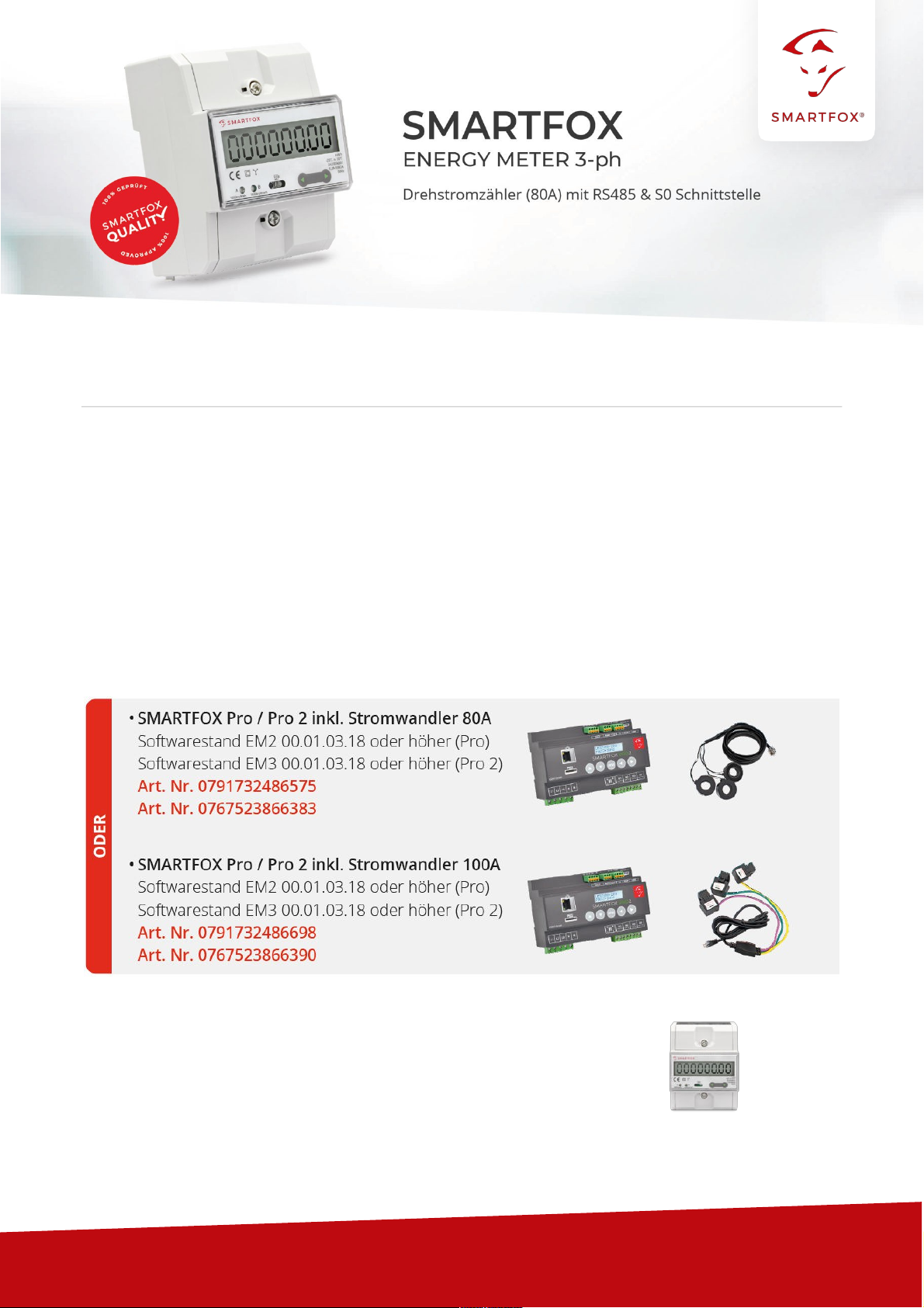
"SMARTFOX Energy Meter
Art. No. 0767523866321
V1.0-06.2022

www.smartfox.at
2
Table of contents
1
Connection..............................................................................................................................................3
1.1
AC
connection .............................................................................................................................................3
1.2 Communication...........................................................................................................................................3
2 Settings on the SMARTFOX Pro (RS485 connection)
.......................................................................
4
2.1 Function subcounter ..................................................................................................................................9
2.2 Function WR1 - WR5 ..............................................................................................................................11
2.3 Function CC1 - CC5 ................................................................................................................................14
2.4 Own" function ...........................................................................................................................................16
3 Settings on SMARTFOX Pro (connection S0)
...................................................................................
17
3.1 Inverter function........................................................................................................................................18
3.2 Function consumption meter ..................................................................................................................20
4
Notes.......................................................................................................................................................21
Copyright
We have checked the contents of this documentation for conformity with the hardware and software described.
Nevertheless, deviations, remaining errors and omissions cannot be ruled out, so that we cannot accept any liability
for any damage that may result. However, the information in this publication is checked regularly and any
necessary corrections are included in subsequent editions. We are grateful for any suggestions for improvement.
This original documentation is protected by copyright. All rights reserved, in particular the right of reproduction and
distribution as well as translation. No part of this manual may be
reproduced
in any form (by photocopy, microfilm or
any other process)
or stored, processed, duplicated or
distributed
using electronic systems
without written permission
from
DAfi GmbH.
Contraventions may result in penal consequences.
All rights & technical changes reserved.
© DAfi GmbH, Shutterstock;
www.smartfox.at
3
1
Connection
1.1
AC connection
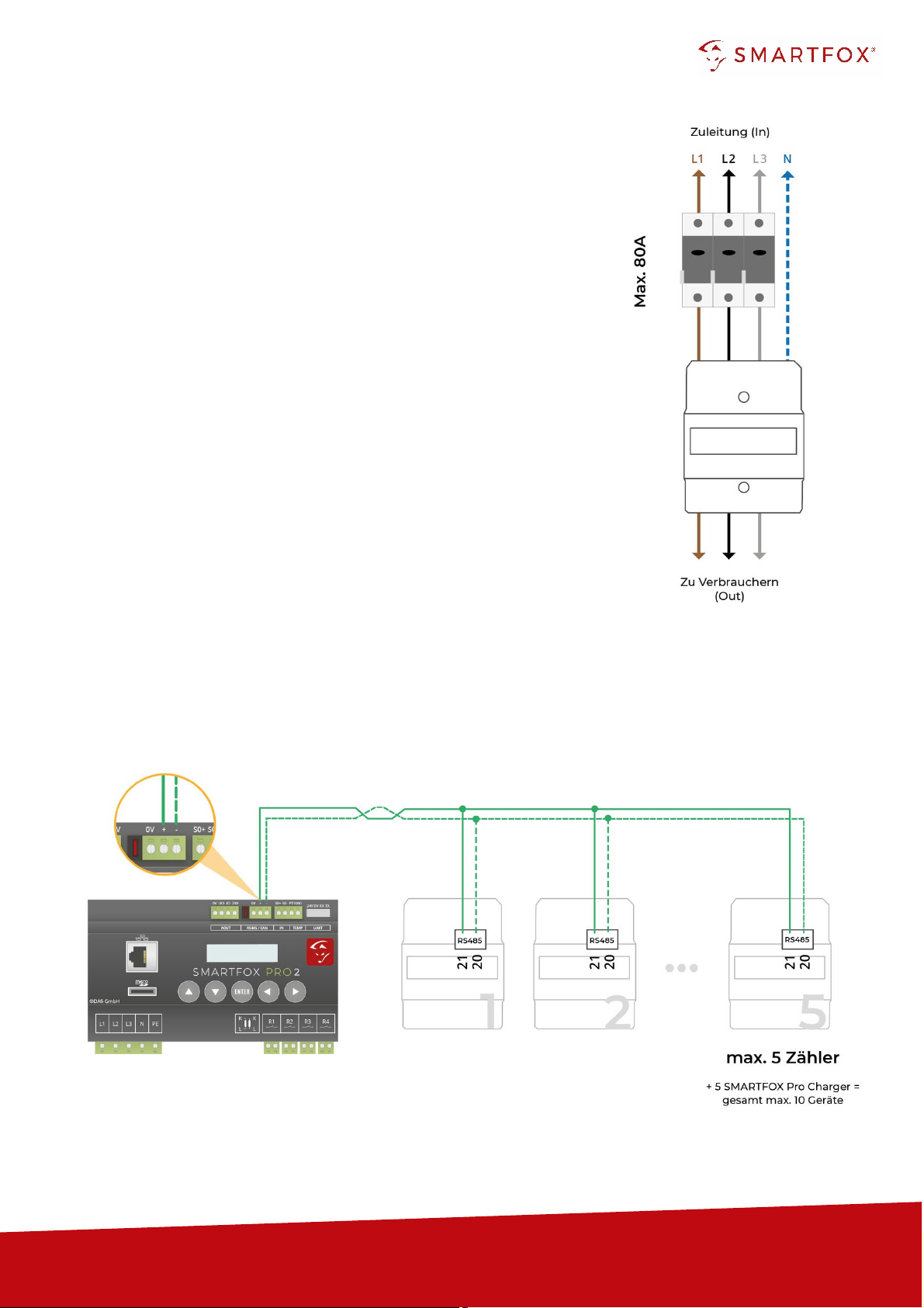
Connect the phases to be measured L1, L2, L3 & N to the corresponding
terminals on the meter (Fig. right).
Pay attention to the input and output side.
1.2
Communication
Two interfaces are available on the meter for communication (RS485 or S0
signal). In general, the use of the RS485 interface is recommended in order
to be
able to
display the data in real time in the portal.
The S0 signal transmits the energy values in pulses. The corresponding
power value is calculated via a minute average.
1.2.1
Connection via RS485 (Modbus RTU)
Up to 5 SMARTFOX Energy Meters can be added to the bus. In addition, up to 5 SMARTFOX Pro
Chargers can be operated on the same bus (10 devices in total). For this purpose, use a twisted pair of
wires of a shielded cable (e.g. CAT6).
www.smartfox.at
4
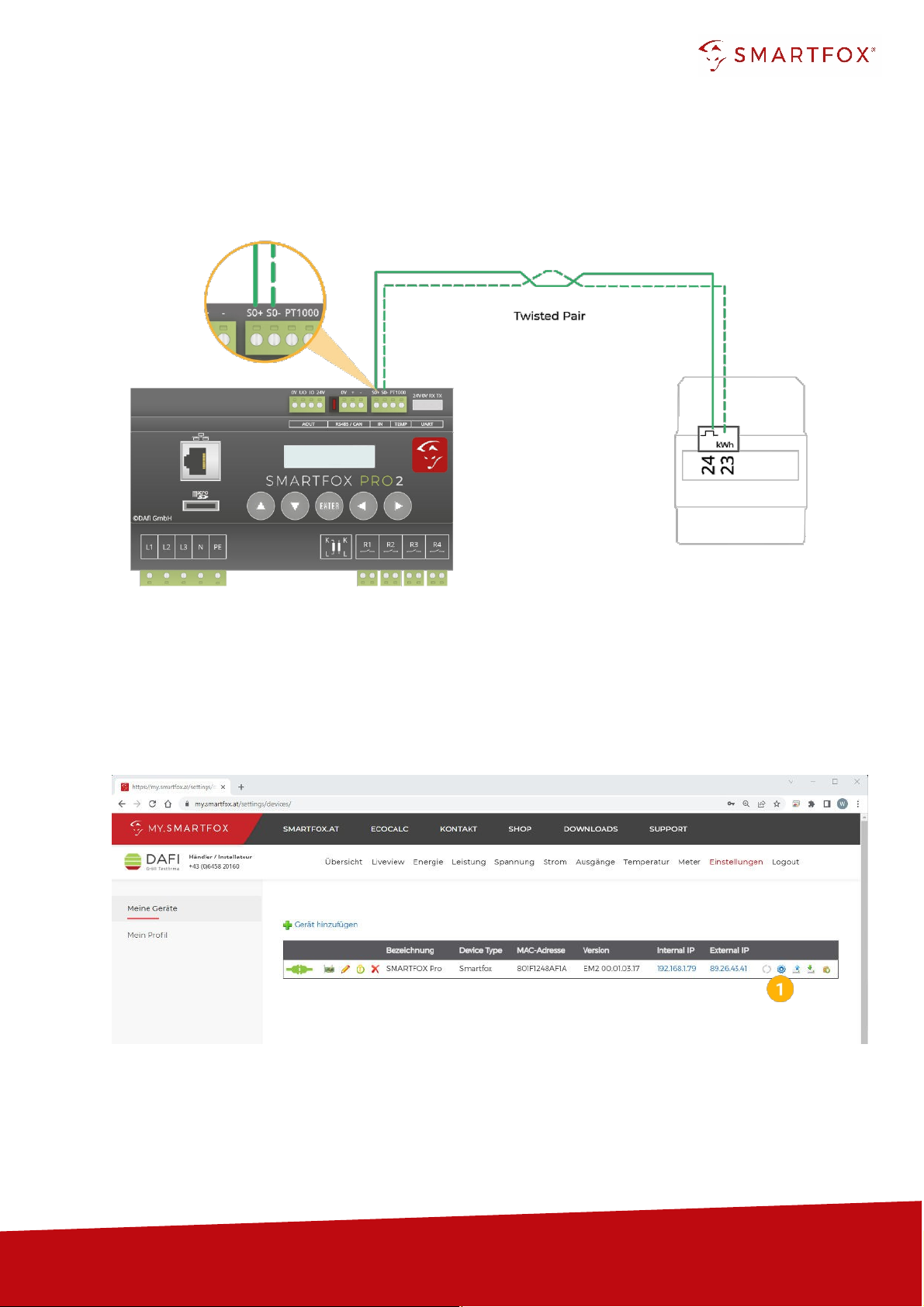
1.2.2
Connection via S0 signal
If the RS485 interface of the energy manager is already occupied, a SMARTFOX Energy Meter can
be read in
via S0
signal. For this purpose, use a twisted pair of wires of a shielded cable (e.g. CAT6).
2
Settings on the SMARTFOX Pro (RS485 connection)
1.
Call up the web portal "my.smartfox.at" and log in.
Select the menu "Settings" 🡒"My devices" and
open
the device parameterisation of the SMARFOX Pro
(cogwheel).
www.smartfox.at
5
2.
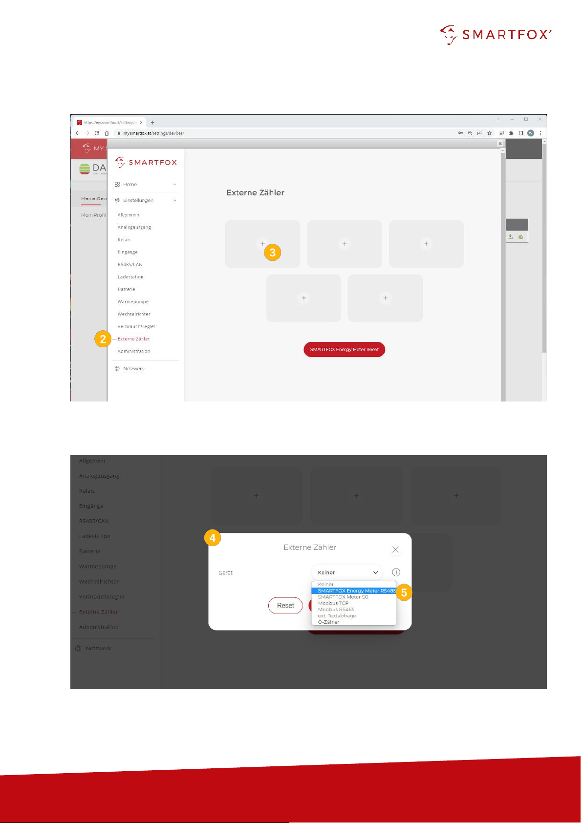
Select the submenu "External counters".
3.
Select a free field by clicking on it.
4.
The pop-up window opens.
5.
Select "SMARTFOX Energy Meter RS485" in the drop-down menu.
www.smartfox.at
6
Note! If several participants are connected to the bus, make sure that
only the participant to be
parameterised is switched on
before starting the
configuration. Once the first participant has been
configured, switch it off and switch on the next participant.
Start the configurator for the additional meter or charging station and repeat the steps until all participants
have been integrated. After configuration, all participants can be switched on.
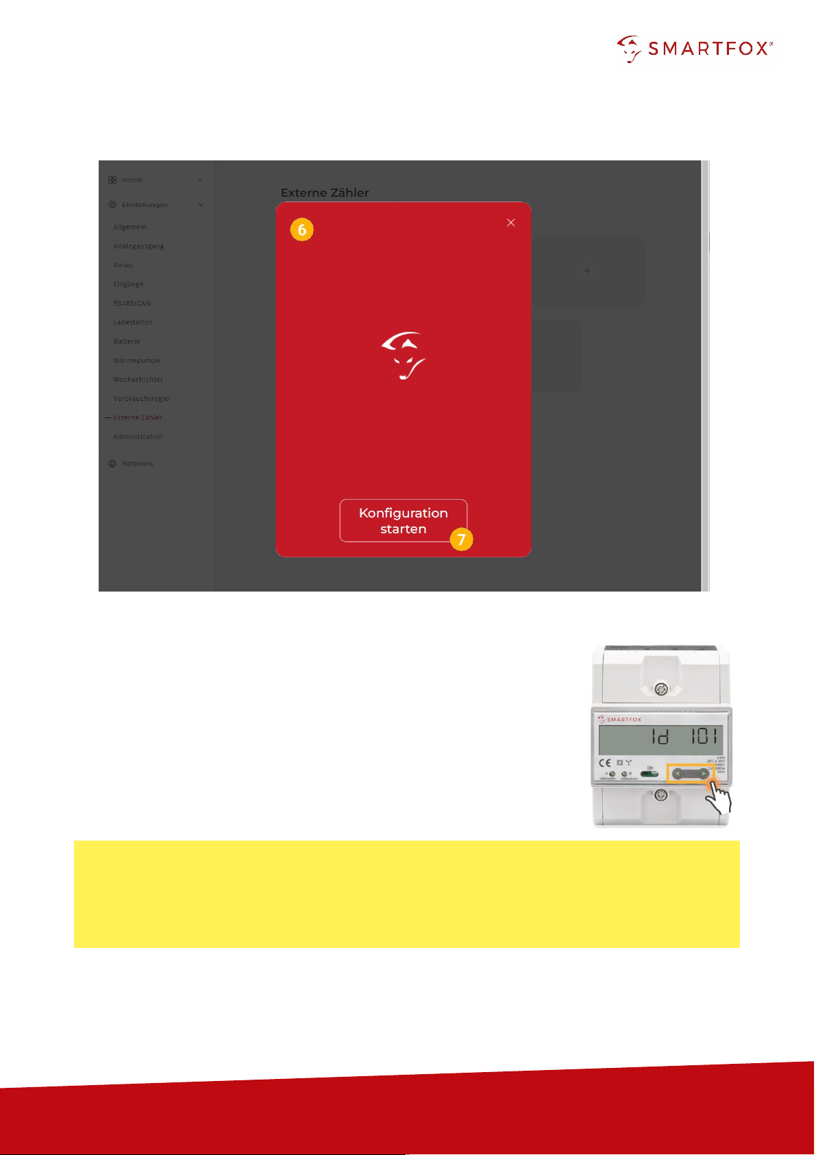
6.
The commissioning wizard is called up.
7.
Click on "Start configuration".
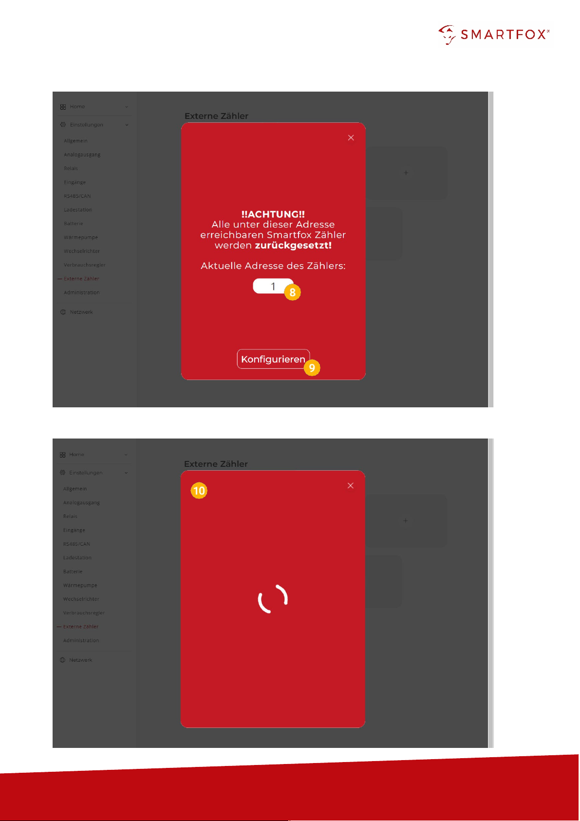
8.
Enter the current address (ID) of the meter. Factory setting ID=1, no
change required.
The counter is automatically
assigned
a new ID by the configuration.
The counter at place 1 receives ID=101, counter 2 ID=102 ... counter 5
ID=105.
If the meter was already in operation, the current ID can be read on the
display. By means of touch-sensitive keys (fig. right: green arrows), you
can navigate through the menu until the ID is displayed.
www.smartfox.at
7
9.
Click on "Configure".
10.
The counter is configured.
www.smartfox.at
8
Hint! If the configuration could not be completed, the SMARTFOX issues an error message. Check the
RS485 cabling, power supply of the participant and repeat the steps.
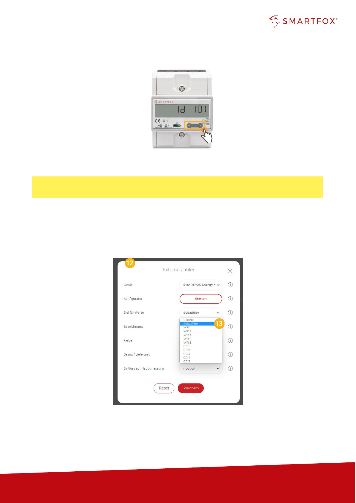
11.
After the configuration is complete, the ID can be checked on the meter.
12.
If the configuration of the bus address (ID) was successful, the other settings can be made.
13.
Under "Target for values" the function of the counter can be defined. The individual functions
are described in points 2.1 to 2.4.
www.smartfox.at
9
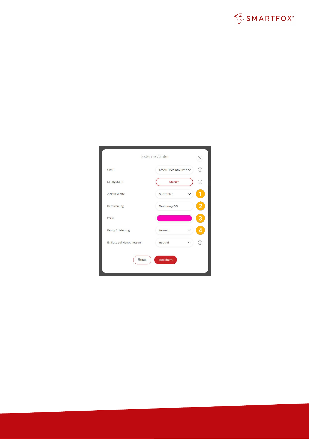
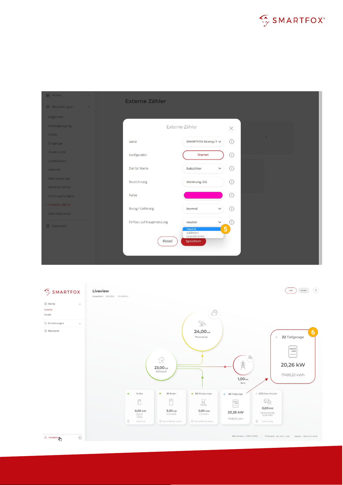
2.1
Function subcounter
The "Sub-meter" function can be selected to connect various consumers to the monitoring (e.g. flat
meter, heat pump meter, general consumer...).
1.
Select "Sub-counter" under Destination for values.
2.
Under Designation, the name is given with which the meter is displayed in the portal.
3.
The counter is displayed with the selected colour in the portal.
4.
The "Supply / Delivery" setting can be used to change the counting direction if the input and
output have been reversed when connecting the meter.
www.smartfox.at
10
5.
This setting can be used to define the influence of the counter on the main measurement.
Neutral: The power value of the meter has no influence on the main measurement.
Add: The power value of the meter is added to the main measurement.
Subtract: The power value of the meter is subtracted from the main measurement.
6.
The measured values can now be read in LiveView, power charts, energy charts, ....
Table des matières
Manuels Instrument de mesure populaires d'autres marques


Endress+Hauser
Endress+Hauser Proline Promag 50 Caractéristiques techniques

Siemens
Siemens SITRANS F Coriolis FCT030 Manuel de la liste des pièces

KLINGER
KLINGER CMF V Series Manuel utilisateur

EXFO
EXFO FTB-2 Manuel d'exploitation et d'entretien

Keysight
Keysight M8290A Manuel utilisateur

ADTEK
ADTEK MW-5 Manuel utilisateur