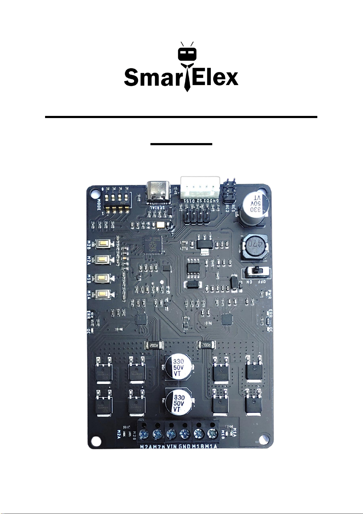
SmartElex 10D Dual Channel DC
Motor Driver (Powered by Raspberry Pi)
3
Introduction:
SmartElex 10D is a dual channel motor driver capable of supplying 10
amps continuous with peak currents up to 25 amps (10Sec) per channel. It
can be operated from radio control, analog, TTL serial and PWM. A variety
of operating modes including with mixed and independent mode in radio
control, analog and in PWM mode. Operating modes allow for operation,
such as switching between radio controls and PWM mode or switching
between any of 4 modes via 4 position DPDT mode switch.MOSFETs are
switched at 16 KHz to ensure quiet operation and no annoying whining
sound. Besides, it also equipped with a microcontroller unit to provide smart
features such as multiple input modes and current limit and thermal
protection. If temperature of board is reaches 80 degree then motor speed
becomes half and speed will be normal once temperature reaches below 70
degree. Motor driver will be shut down at 100 degree.