SmartCockpit Fokker 50 Manuel utilisateur

FLIGHT CONTROLS
The flight controls can be operated manually and automatically. From the flight deck, all
control surfaces are mechanically operated via rod-and-cable systems, except the electrically
operated aileron trim tab. To augment pitch attitude stability, an augment pitch attitude
stability system is installed. When the autopilot is engaged, ailerons, rudder, elevator, and
elevator-trim tab are controlled automatically.
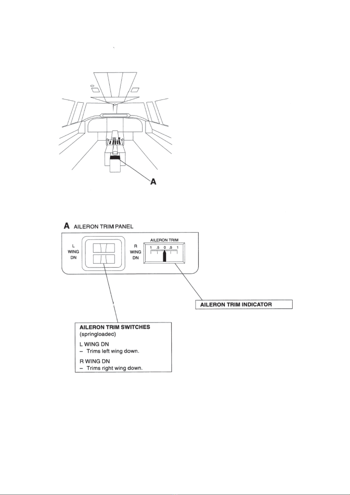
Ailerons
The ailerons are operated manually from the captain’s and first officer’s control wheels. The
ailerons are equipped with spring tabs and balance tabs. The balance tab at the RH aileron
can be electrically operated as a trim tab. The aileron trim control panel is installed at the
rear of the pedestal.
Rudder
The rudder is operated manually from the captain’s and first officer’s pedals. A trim tab and a
balance tab, one above the other, are attached to the trailing edge of the rudder. The trim tab
can be operated mechanically from the trim control panel on the pedestal.
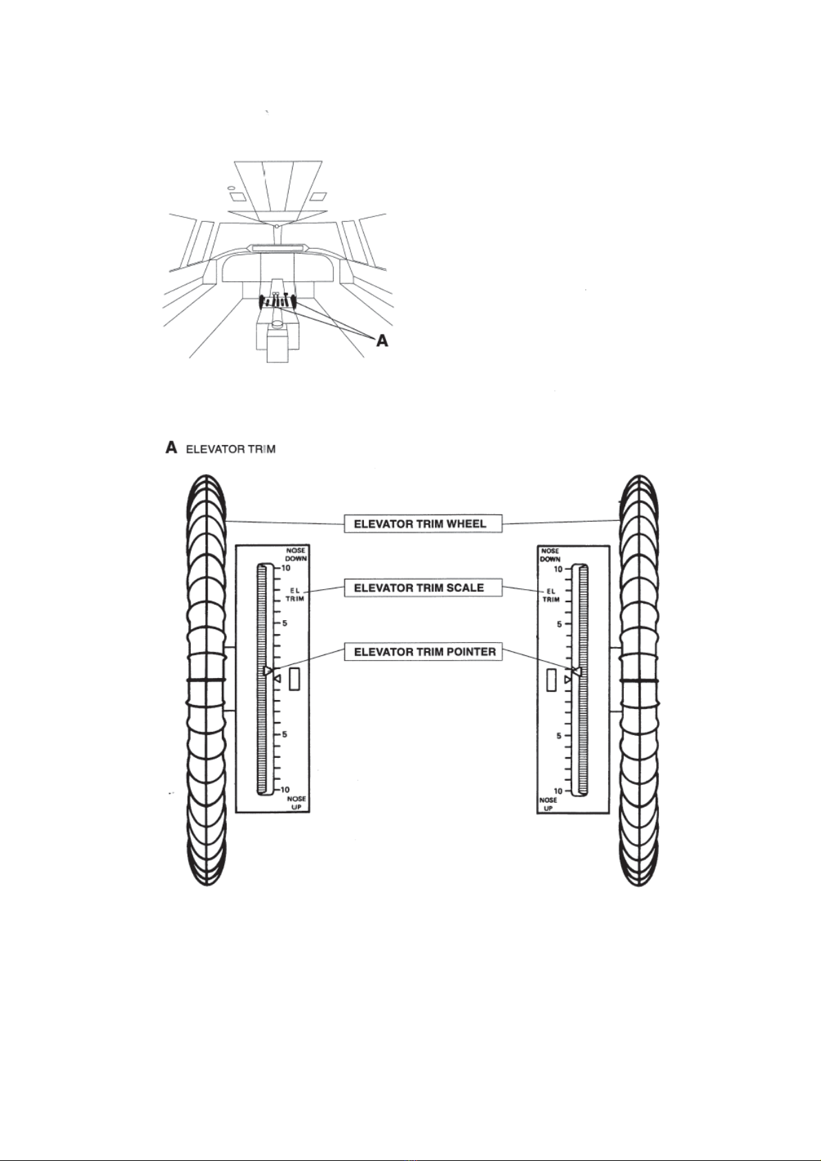
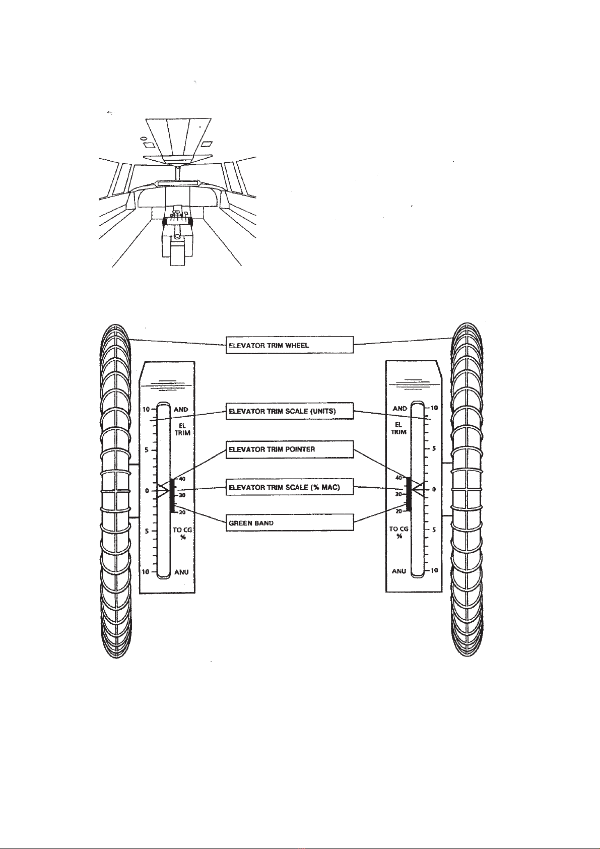
Elevator
The elevators are operated manually from the captain’s and first officer’s control column.
Pitch trim is obtained by an elevator trim tab at the RH elevator. The trim tab is operated by
trim wheels on both sides of the pedestal. A position indicator near each control wheel shows
the trim setting.
Augment pitch attitude stability
There are two pitch stability systems:
• Elevator Feel Control System.
• Longitudinal Stability Augmentation System.
Type I
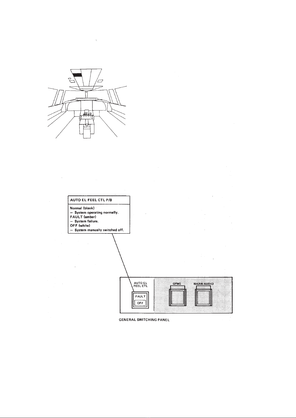
An automatic Elevator Feel Control System (EFCS) is provided to balance the out-of-trim
forces caused by transients due to power and flap selections that would otherwise be felt at
the control column. The system operation is automatic and is active only during flight. Flap
and power lever positions are used as input variables. If the system fails, an alert will be
presented. The fault annunciation due to the power levers and flaps is inhibited during flight,
the alert will be presented on the ground approximately 15 seconds after landing. The
system can be switched OFF with the AUTO EL FEEL CTL pushbutton at the general
Fokker 50 - Landing Gear & Flaps
Page 1

switching panel. Once switched OFF, the system cannot be reinstated from the flight deck. If
the system is switched OFF, or has failed, the elevator operation is not affected. The elevator
control forces will now be defined by the position in which the feel control unit ceased
operation. On the ground an automatic self-test of the system is initiated when the flight
control lock is engaged, and the system is placed into a parked condition.
Type II
The Longitudinal Stability Augmentation System (LSAS) is provided to correct for the
dynamic out of trim farces caused by changes in engine power, flap position and aircraft
speed, and to augment the longitudinal stability at forward CG in flight. System operation is
automatic and active during flight only. Inputs are provided by:
• Both Electronic Engine Control (ENG EC) units.
• Attitude and Heading Reference System no 1 (AHRS 1).
• Flap drive unit.
• Air Data Computer (ADC).
NOTE: For those aircraft equipped with two ADC’s, ADC 1 is used as input for this
system.
The system uses the inputs to vary the bungee spring tension. Controls and indicators are
installed at the general switching panel, located at the overhead panel. A DEGRADED light
indicates a system input failure (flap position, airspeed or pitch). A FAULT light in the STAB
AUG pushbutton indicates a complete system failure. In this case LSAS will freeze in its last
position. The system can be switched OFF by depressing the STAB AUG pushbutton. With
the DEGRADED or FAULT lights illuminated, or the system switched OFF, the elevator
control forces during manual flight may be slightly higher or lower than normal, depending on
flight phase. Some system input failures (power lever and flap positions) detected in flight will
result in a system failure alert after landing (15 seconds after touch down). On the ground an
automatic self-test of the system is initiated when the flight control lock is engaged, and the
system is placed into a parked condition.
Pre-stall warning
If the aircraft attitude approaches a stall condition, a stick shaker at the LH control column is
activated. Shaker activation will disengage autopilot and yaw damper. The angle-of-attack
vane is located on the RH side of the fuselage nose. The pre-stall warning, which operates
independent of the integrated alerting system, is armed in flight only.
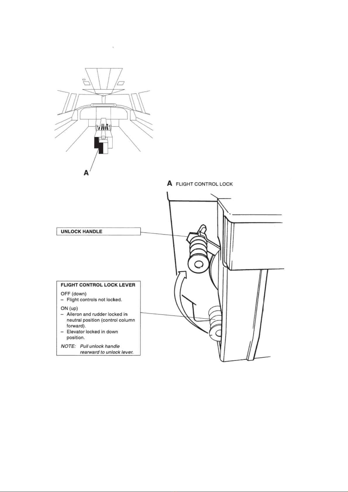
Flight control lock
A mechanically operated system of locks is provided for the ailerons, the rudder, and the
elevators. This system locks the ailerons and rudder in neutral position and the elevators in
down position. Each lock is spring loaded to the unlocked position. The EFCS or LSAS
control unit is commanded to a parking position. When the flight controls are locked, then the
power levers are prevented from being set to take-off power simultaneously. The flight
control lock lever is located at the rear LH side of the pedestal.
Fokker 50 - Landing Gear & Flaps
Page 2
Controls and indicators
Controls and indicators - Type I
Fokker 50 - Landing Gear & Flaps
Page 3

Controls and indicators - Type II
Fokker 50 - Landing Gear & Flaps
Page 4
Controls and indicators - Type I
Fokker 50 - Landing Gear & Flaps
Page 5
Controls and indicators - Type II
Fokker 50 - Landing Gear & Flaps
Page 6

Fokker 50 - Landing Gear & Flaps
Page 7
Fokker 50 - Landing Gear & Flaps
Page 8
Fokker 50 - Landing Gear & Flaps
Page 9
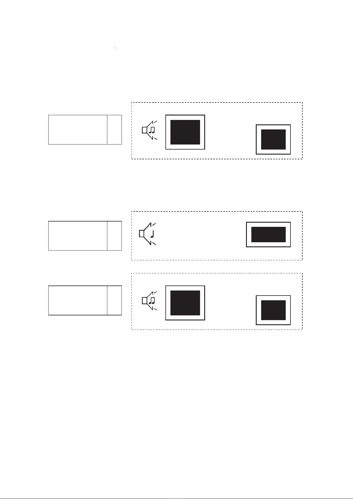
Alerts
Alerts - Type I
Alerts - Type II
AUTOMATIC ELEVATOR
FEEL CONTROL
SYSTEM FAILURE
2
AURAL MWL/MCL CAP LOCALCONDITION(S) / LEVEL
CAUTION
FAULT
AUTO EL
FEEL CTL
LONGITUDINAL
STABILITY
AUGMENTATION
SYSTEM FAILURE
2
CAUTION
FAULT
STAB AUG
LONGITUDINAL
STABILITY
AUGMENTATION
SYSTEM FAILURE
1
AURAL MWL/MCL CAP LOCAL
CONDITION(S) / LEVEL
DEGRADED
Fokker 50 - Landing Gear & Flaps
Page 10
Table des matières
Autres manuels SmartCockpit Aéronef


