smart-MAIC D103 Manuel utilisateur

Version 1.0
USER GUIDE
smart-MAIC D103
Measure, Analyze,
Improve and Control,
.... be smart!

USER MANUAL
2
CONTENT
I. Introduction ........................................ 3
Purpose of the device and its functions ............. 3
Controlled output .................................. 3
Location of device components ..................... 4
Device status indicator ............................. 4
II. Getting Started ..................................... 5
Installation and connection......................... 5
III. Connection diagram ................................ 6
IV. Data check ......................................... 8
V. Connecting to your wireless network ............... 9
VI. Reboot and recovery factory settings............... 11
VII. Maintaining your device ........................... 11
VIII. MQTT Service ..................................... 12
IX. Terms and Conditions ............................. 13
X. Scope of delivery .................................. 14
XI. Specifications ..................................... 15
XII. Access to data. Visualization....................... 15

3
Purpose of the device and its functions
The device is designed for continuous measurement of electrical
network parameters and electricity consumption.
The device measures the following parameters:
• voltage, V
• current strength, A
• active power, W
• reverse * active power, rW
• active energy, Wh
• reverse * active energy, rWh
• Power factor
* parameters are available in the extended version of the device
Communication with the device is carried out via the IEEE 802.11
Wi-Fi 2.4 GHz wireless communication protocol.
The device transfers the accumulated data to the "cloud" server
for further analysis and visualization. For more information about
the processing capabilities of the data received from the device,
see the WEB page www.smart-maic.com.
Current data is also available on the built-in WEB site of the
device.
Controlled output
The device is equipped with a controlled dry contact output.
The controlled output is intended for automation of load control.
The output can control power solid-state relays to which
electrical appliances are connected, or for building automation in
low-current networks.
The output is controlled remotely, on the device's WEB page or
from the server. It is also possible to control the output according
to predefined conditions and / or schedule.
Thank you for purchasing the smart-MAIC 103 Energy Monitor.
This device allows you to measure and record changes in electricity
consumption and power grid parameters in three phases or three
lines in a single-phase network.
I. INTRODUCTION

The controlled output is intended for switching power loads no
more than 50W.
Location of device components
The device is made in a housing for installation on a DIN rail with
an IP20 protection level. When installing at the monitoring object,
it is necessary to use a mounting box made of plastic with a level
of dust and moisture protection IP54 for indoor installation or IP65
for outdoor installation. For outdoor installations, avoid direct
sunlight.
The figure shows the main components of the device.
2
4
3
1
Вид сверху
Device status indicator
The device status indicator is located on the front panel. The
indicator signals the following device states:
The indicator state Device status
The indicator
flashing quickly
Search is performed and
wireless network connection
The indicator
flashing slowly
The built-in access point is activated, it
is possible to connect to the device to
configure the parameters
The indicator is on
continuously
The device connected
to the wireless network
The indicator does not
work
- the device is turned off, or
- defective or
- indicator is off in settings
1 Upper group
of contacts for
connecting current
transformers
2 Reset button
3 Bottom group of
contacts for power
connection
4 Device status
indicator
USER MANUAL
4

Installation and connection
The device can be installed in an electrical panel on a DIN rail.
Follow the steps below to install the device:
1. Mount the device on a DIN rail.
2. Secure the device by sliding the latch up.
The connection of the device to the mains must be carried out by
trained personnel with a permit of at least group III for electrical
safety when working on installations up to 1000 V
To connect the device, run next steps:
1. Connect the leads of the current transformers to the device
according to the wiring diagram. If your transformers are
equipped with a quick plug, do not connect them to a running
device. Connecting a transformer plug to an operating device
may damage the device.
2. Slide the current transformers over the wires of the 1st, 2nd and
3rd phase. Current transformers are numbered (1-2-3) and have a
power direction indicator. It is accepted that the energy moves in
the direction from the electricity meter towards the consumers.
Installing the currenttransformers in accordancewiththe energy
direction indicators will give the best measurement accuracy.
3. Connect three phases and a neutral wire to the device in
accordance with the connection diagram.
II. GETTING STARTED
5

III. CONNECTION DIAGRAMS
Conditional connection diagram in a 3-phase network
Connection diagrams of current transformers and power lines for
different device modifications
A WARNING:
Do not put
unconnected
current transformers
on the wire.
This can damage
the transformers.
Upper contact group
1 controlled output
2 controlled output
3 current transformer No. 1,
red wire
4 current transformer No. 1,
black wire
5 current transformer No. 2,
red wire
6 current transformer No. 2,
black wire
7 current transformer No. 3,
red wire
8 current transformer No. 3,
black wire
Connecting transformers
to Jack 3.5 connectors
Upper contact group
1 controlled output
2 controlled output
3 current transformer No. 1
4 current transformer No. 2
5 current transformer No. 3
Lower contact group
General connection diagram
to consumer
Zero Phase 3 Phase 2 Phase 1
Transformers 100A and Rogowski rings
1000A / 1500A / 2000A
6USER MANUAL

Transformers
300А/600А/1000А/1500А
Upper contact group
1 controlled output
2 controlled output
3 current transformer No. 1,
white wire
4 current transformer No. 1,
black wire
5 current transformer No. 2,
white wire
6 current transformer No. 2,
black wire
7 current transformer No. 3,
white wire
8 current transformer No. 3,
black wire
The smart-MAIC D103 energy
monitor is a 3-line device that
can be installed in a single-
phase network to monitor
lines to different consumers
(boiler, air conditioner, kitchen,
sockets, lighting, etc.)
Connect power to one of the
inputs and set jumpers for the
remaining power inputs L1 L2
L3.
Connect the current trans-
formers and put them on the
corresponding lines that go to
the consumers.
Smart-MAIC D103 connection in a single-phase network
7
to consumer

It is important to understand how the data from the smart-MAIC
energy monitor is saved at different time intervals. It is especially
important to understand the calculation principle for the Power
[W] parameter when it is converted from electrical power into
electrical energy.
As mentioned, there is an arrow on every current transformer. If
the arrow is positioned towards the consumer, the monitoring data
will be saved as follows:
- active power (consumption) in the [W] Power parameter;
- reversible active power (generation) in the [rW] Revers Power
parameter;
- accumulative meter of consumed energy in [Wh] Energy;
- accumulative counter of reversible energy in [rWh] Energy.
Energy Monitor
Data, Designation
Current readings and
minute interval
Hourly, daily, weekly, monthly,
yearly interval
Voltage, V1 V2 V3 Voltage in [V] Average arith. in [V]
Current, А1, A2, A3
и TA (total) Current in [A] Arithm mean. in [A]
Power, W1, W2, W3
и TW (всего)
Instantaneous active
power [W] or [W]
Active energy for a period [Wh]
or [W * h]
Reverse Power,
rW1, rW2, rW3и
TrW (всего)
Instantaneous reversible
active power [W] or [W]
Reversible active energy per
period [Wh] or [W * h]
Power Factor, PF1,
PF2, PF3
Power factor
(cosF)
Arithmetic mean power factor
(cosF)
Energy, Wh1, Wh2,
Wh3 и TWh (всего)
Cumulative electricity
meter [Wh] or [W * h]
The same, cumulative electricity
meter [Wh] or [W * h]
Reverse Energy,
rWh1, rWh2, rWh3
и TrWh (всего)
Cumulative counter of
reversible electricity [Wh]
or [W * h]
The same, accumulative
counter of reversible electricity
[Wh] or [W * h]
IV. MEASURED DATA

For normal operation of the device, it is necessary, in the place of
its installation, to provide a good signal of your wireless network
with Internet access. When you start it for the first time or after
a short press on the Reset button, the device enters the wireless
access point mode.
V. CONNECTION
TO YOUR WIRELESS NETWORK
On your computer or phone, go to the list of wireless networks
and select the smart-MAIC0123456789 network connection. If the
“smart-MAIC” + network (your device number) is absent, briefly
press the Reset button on your device. The default connection
password is no.
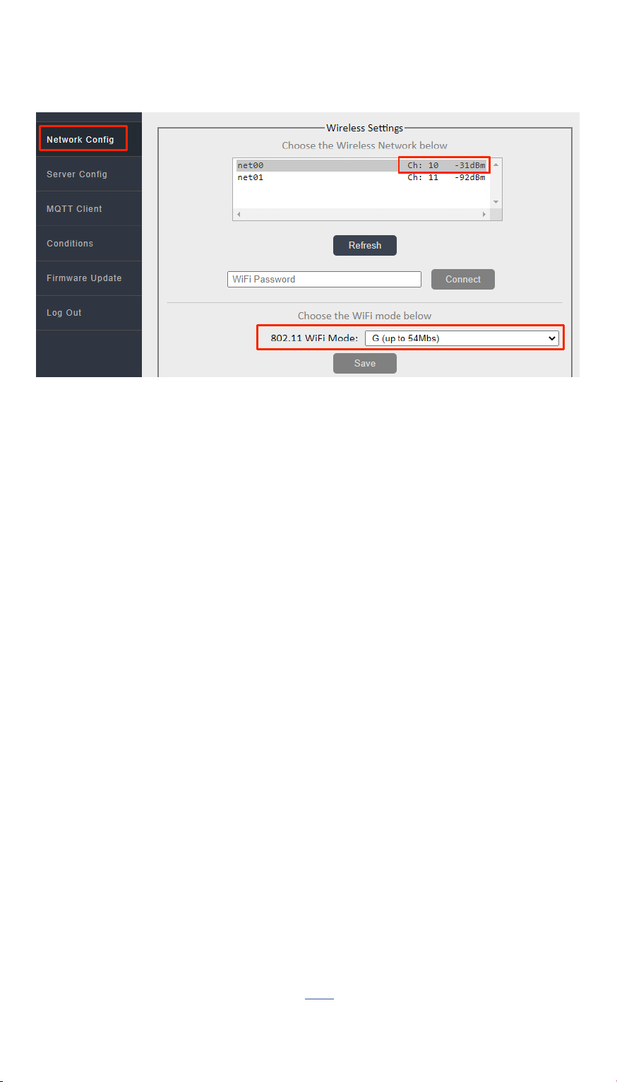
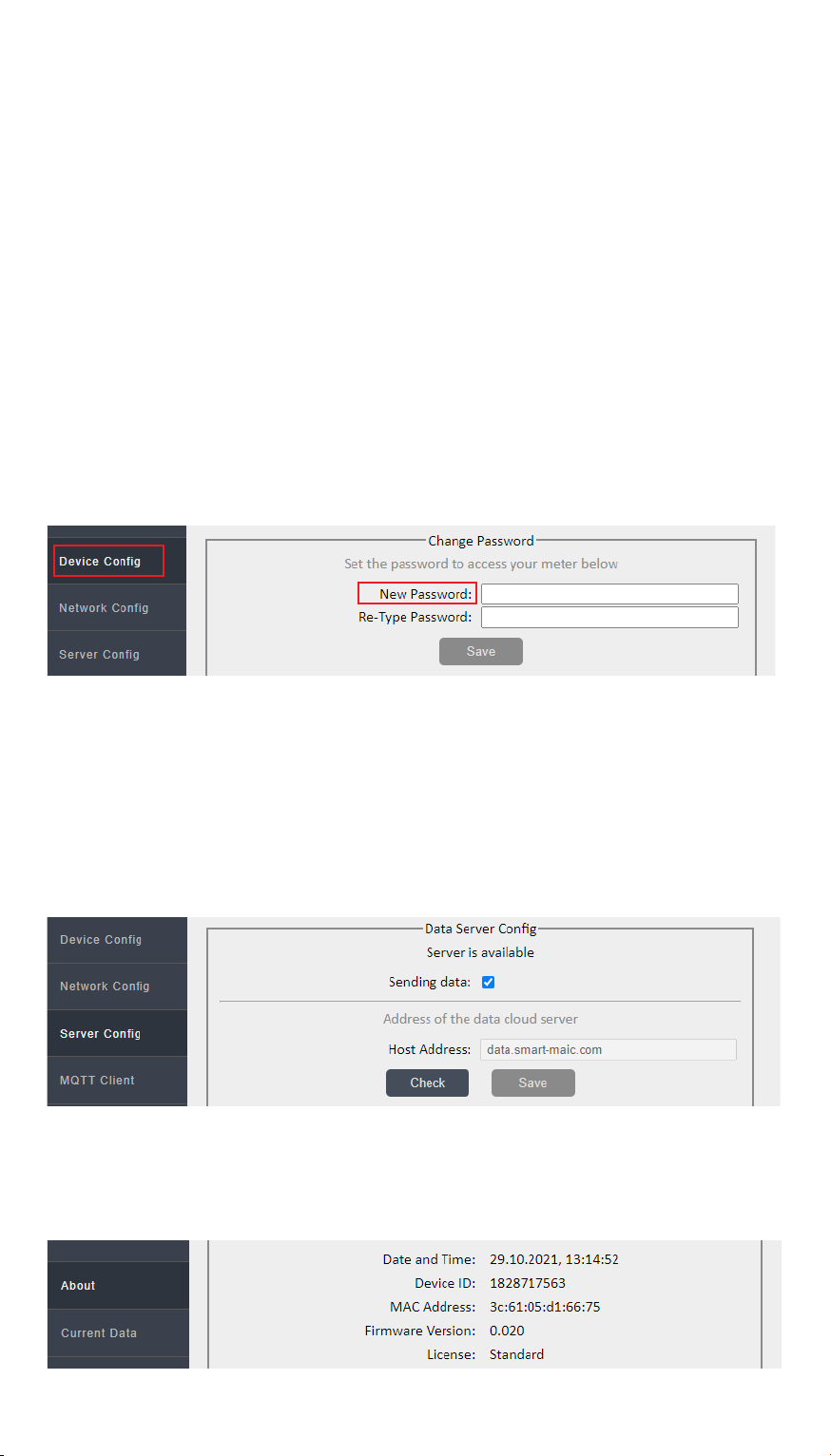
After successful connection, enter http://192.168.4.1 in the
address bar of the browser and go to the built-in WEB site of the
device.
In the "WiFi and Network" section, select your network name
from the list of wireless networks, click the "Connect" button and
enter your network password.
If there is no name (SSID) of your network in the list of wireless
networks, refresh the list by clicking the "Refresh" button.
Wait a minute and reconnect to the device's access point again.
Reload the device settings page and make sure that the connection
is successful and the device's internal IP address is in the status
bar. Disconnect from the device's hotspot and connect to your
WiFi network. Go to the built-in WEB site of the device using the IP
address obtained when connecting and continue configuring the
parameters.
If you still have questions about connecting to your network, look
at additional information on this link

USER MANUAL
8
If you are having difficulty finding a device on your network, use
the search utility.
General tips if you are having problems connecting to WiFi:
1. For stable operation, the signal level must be greater than
-80dB, i.e. better than -70dB.
2. Try changing the WiFi type to "G (up to 54Mbs)" in the device
settings.
3. Try changing the channel on your router.
4. Try connecting the device to a different router to diagnose the
problem.
The default password 0000 will not allow you to connect devices
to your account on the "cloud server".
The password must consist of numbers and be no more than 10
in length. Your new password will allow you to access data from
your device stored on the "cloud server".
In the "Data Server" section, check the connection of the device to
the "cloud" server.
In the "Status" section, look at and copy the device ID for yourself.
You will need the device ID to connect the device to the "cloud
server".
In the "Configuration" section, select the language of the WEB
interface convenient for you. Change the password for entering
the WEB interface of the device.
Table des matières
Manuels Instrument de mesure populaires d'autres marques

Endress+Hauser
Endress+Hauser Proline Promag 50 Caractéristiques techniques

Siemens
Siemens SITRANS F Coriolis FCT030 Manuel de la liste des pièces

KLINGER
KLINGER CMF V Series Manuel utilisateur

EXFO
EXFO FTB-2 Manuel d'exploitation et d'entretien

Keysight
Keysight M8290A Manuel utilisateur

ADTEK
ADTEK MW-5 Manuel utilisateur


