Sitro Group Gasmate AVENIR Manuel utilisateur

1
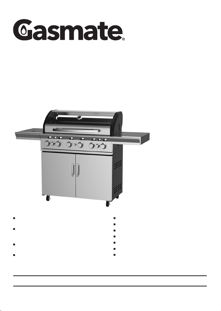
Enhance your outdoor area with a Gasmate Avenir 6
burner BBQ complete with rear ceramic rotisserie burner
Create the ultimate outdoor kitchen by adding a
Gasmate Avenir Sink, Storage and/or Fridge Module to
your BBQ (sold separately)
Double skinned 304 grade stainless steel roasting
hood with viewing window and temperature gauge
304 grade stainless steel fascia, side shelves and
cabinet doors with powder coated cabinet trolley
Flush mounted side burner for greater cooking versatility
Cast iron hotplates and grill with enamel warming rack
Stainless steel tubular burners lit by electronic ignition
Complete with hose and regulator
Assembled dimensions (mm): 1700W x 1180H x 580D
Total cooking area (mm): 960W x 460D
Approved to Australian and New Zealand Standards
Important: Retain these instructions for future use.
5201-07/20
Gasmate® is a registered trademark of: Sitro Group Australia Pty Ltd www.gasmate.com.au
Aber Living - Hamilton, N.Z. www.gasmate.co.nz
AVENIR
6 BURNER BBQ
Model No. GM172-054

32
GENERAL INFORMATION
Gas Installation Codes
• Barbecues must be used in accordance with New
Zealand Standard 5601 “Gas Installations”.
• Barbecues for use with bottled gas are labelled ‘LPG/
ULPG’.
• Barbecues for use with natural gas are labelled ‘natural
gas’ and must be installed by an authorised person.
Check the gas type sticker attached to the barbecue.
Clearances
Minimum Clearances from combustible materials must be:
Rear - 600mm Sides - 600mm Above - 600mm
Specifications
Barbecue specifications can be found on the data label
attached to the door panel or the barbecue body.
Hose & Regulator Safety
The regulator and hose assembly supplied with the
barbecue are suitable for LPG only. Hose connection
thread is G1/4-19.
A gas regulator adjusted to have an outlet pressure of
2.75kPa is supplied for connection to the LPG cylinder.
The pressure regulator and hose assembly supplied
with the barbecue must be used. Replacement pressure
regulators and hose assemblies must be those specified
by the barbecue manufacturer.
When connecting the hose and regulator assembly to the
gas cylinder, take care to avoid unnecessary twisting of
the flexible hose.
After the assembly has been secured, turn on the gas
and check for leaks by brushing a soap and water
solution over all connections.
If you are unable to correct the leak by tightening the
connections, turn off the gas and contact the supplier
immediately.
Always ensure the barbecue is kept away from flammable
materials and the gas cylinder clear of any heat source.
When changing over from an empty gas cylinder to a
full one make sure this procedure is carried out in a well
ventilated location, preferably outside, away from people
and away from any sources of ignition; such as naked
flames, pilot flames, electric heaters/equipment.
Gas Cylinder Use & Safety
This is a low pressure barbecue and must only be used
with the hose and regulator supplied. Your barbecue is
designed for use with 9Kg LPG cylinders.
The gas cylinder should be filled by a reputable gas
supplier and visually inspected and requalified at each
filling.
Always keep cylinder in an upright position. Always close
the cylinder valve when the barbecue is not in use.
Do not subject gas cylinder to excessive heat.
NEVER STORE YOUR GAS CYLINDER INDOORS.
If you store your barbecue indoors, ALWAYS disconnect
the gas cylinder first and store the cylinder safely outside.
Cylinders must be stored outdoors in a well ventilated
area out of reach of children, and must not be stored in a
building, garage or any other enclosed area.
IMPORTANT
Read these instruction carefully prior to use.
Familiarise yourself with the appliance before
connecting it to it’s gas container. Keep these
instructions for future reference.
If you smell gas
1. Shut off gas to the barbecue at its
source, if possible.
2. Extinguish any open flame.
3. Open hood.
4. If odour continues immediately call your
gas supplier or fire department.

32
FOR YOUR SAFETY
Failure to comply with these instructions could result
in a fire or explosion which could cause serious
bodily injury, death or property damage.
CAUTION: Accessible parts may be very hot.
Keep young children away.
DO NOT modify this appliance.
DO NOT move this barbecue during use.
Turn off gas supply at the gas cylinder after use.
Parts sealed by the manufacturer or their agent must
not be manipulated by the user. This barbecue is
only to be used and stored outdoors.
• Never operate this barbecue without a regulator.
• Do not test for gas leaks with an open flame.
• If this information is not followed exactly a fire
causing death or serious injury may occur. Do
not store a spare gas cylinder under or near this
barbecue. This barbecue is only to be used and
stored outdoors.
• If there is a leak on your appliance (smell of gas)
immediately attempt to turn off the cylinder valve.
Remove the appliance to a well ventilated location
away from any ignition source. Only check for
leaks outdoors using soapy water. DO NOT try to
detect leaks using a flame.
• Check for leaks by brushing a soap and water
solution over all connections. If you are unable to
correct the leak by tightening the connections,
turn off the gas and contact customer service
immediately.
• Only use the hose assembly as supplied with this
appliance for connection to the cylinder -
DO NOT USE ADAPTORS.
• After use turn the gas cylinder valve off, wait for
the flame to go out, then turn the appliance control
valve off.
• Avoid twisting or kinking the flexible hose.
• Do not store or use petrol or other flammable
liquids in the vicinity of this or any other appliance.
• Do not store empty or full spare gas cylinders
under or near this or any other appliance.
• Never test for gas leaks with a lit match or open
flame. Never light barbecue with hood closed or
before checking to ensure the burner tubes are
fully seated over gas valve orifices.
• Never lean over cooking surface when lighting.
• Never alter or modify the regulator or gas supply
assembly.
GENERAL INFORMATION
• This barbecue must not be used indoors.
• Only use in well ventilated areas.
• CARBON MONOXIDE HAZARD - USING THIS
APPLIANCE IN AN ENCLOSED SPACE MAY
CAUSE DEATH. DO NOT USE IN CARAVANS,
TENTS, MARINE CRAFT, CARS, MOBILE HOMES
OR SIMILAR LOCATIONS.
• This appliance shall only be used in an above
ground open-air situation with natural ventilation,
without stagnant areas, where gas leakage and
products of combustion are rapidly dispersed by
wind and natural convection.
• Ensure the barbecue is set up on a level and
stable surface.
• Do not move the barbecue while in use or when
hot. Remove the drip tray before moving.
• DO NOT replace the grill with an extra hotplate.
The warranty will be voided and it violates the gas
approval, the grill provides the ventilation needed
for the BBQ to operate safely. It is not designed to
be a solid hotplate device.
IF THERE IS A LEAK
• Turn the cylinder off.
• Ventilate the area to disperse gas.
• Check all connections.
• If leak persists, keep the cylinder upright. Keep
skin away from any gas or liquid escaping from the
cylinder.
• Keep the cylinder at least 20 metres away from
any sparks or ignition sources, including electrical
equipment, camera flashes, engines and motors.
• Disperse gas by encouraging maximum ventilation
and spraying with a fine water spray.
IF THERE IS A FIRE
• If the fire is at the barbecue, turn the gas off at the
cylinder. Smother the flames with a wet cloth, fire
blanket or extinguish using a fire extinguisher.
• If the fire is at the cylinder, or you can not get
to the valve to turn the gas off, contact the fire
brigade immediately.
• Using a garden hose, direct the water to the
middle of the cylinder to keep it cool. Try not to
extinguish the flame. At least if the gas is burning,
it won’t be able to build up pressure and explode.

54
GENERAL INFORMATION
Location of your Barbecue
DO NOT use your barbecue in garages, porches,
breezeways, sheds or other enclosed areas. Your
barbecue is to be used OUTDOORS. The barbecue is
not intended to be installed in or on recreational vehicles
and/or boats and should not be placed under any surface
that will burn. Do not obstruct the flow of combustion
and ventilation air around the barbecue housing.
Protect Children
Keep children away from barbecue during use and until
barbecue has cooled after you have finished.Do not allow
children to operate barbecue.
Always ensure that no sporting or physical activities are
carried out in close proximity to the barbecue during use
and while still hot.
General Assembly
Remove the barbecue and components from the packing
carton. Check against parts list and lay components out
within easy reach. Do not throw the carton away, unfold
flat and use as a protective work surface. Contact your
supplier for replacement parts if necessary.
Tools You Will Need
Standard Phillips-head screw driver (or cordless drill
and bits) and Adjustable spanner (open ended shifter) or
spanners.
Check Barbecue for any Damage
Inspect barbecue parts as you proceed. Contact your
supplier for assistance regarding replacement of any
damaged or missing parts. Do not assemble or operate a
barbecue that appears damaged. Barbecues for use with
gas cylinders are labelled ‘LPG/ULPG’. Check labelling at
the gas connection on your barbecue.
Kitchen/Module Installation
Modules can only be installed to the right hand side of
the BBQ. The side burner MUST NOT be removed.
Leave at least 200mm of distance between the back
of the unit and the wall for ventilation. All units must be
undercover.
Nominal Hourly Gas Consumption
Gas Type BBQ
Burners
Injector
Size
Gas Consumption
Per Burner MJ/h
Total Gas Consumption
Primary Burners MJ/h
Gas
Pressure
kPa
LPG/
ULPG
6Ø1.0mm 13.5 81
2.75 kPaSide Burner Ø0.95mm 11.5 Total Gas
Consumption MJ/h
Rear Burner Ø1.0mm 13.5 106
ASSEMBLY INSTRUCTIONS
Before assembling the barbecue, read these Instructions
carefully.
Assemble the barbecue on a flat, clean surface.
The barbecue is heavy.
NOTE: Do not fully tighten all the nuts during the initial
stages of assembly.
Caution: Sheet metal can cause injury. Wear gloves
when assembling the barbecue.

54
EXPLODED DIAGRAM
No. Description QTY
1 Fire Box 1
2 Bottom shelf 1
3 Swivel Castor 2
4 Locking Swivel Castor 2
5 Left side panel 1
6 Right side panel 1
7 Upper door bracket 1
8 Back panel 1
9 Top panel 1
10 Left door assembly 1
11 Right door assembly 1
12 Door handle 2
No. Description QTY
13 Fat tray bracket 2
14 Fat tray 1
15 Fat tray front fascia 1
16 R/H side shelf assembly 1
17 L/H side burner assembly 1
18 Side burner grid 1
19 Flame tamer 4
20 Cooking grill 2
21 Hotplate 1
22 Warming rack 1
23 Regulator & hose assembly 1
24 Burner 6
No. Description QTY
25 Crossfire 5
26 Big control knob 6
27 Small control knob 2
28 Ignitor 1
29 Side burner 1
A Screw M6x15 24
B Screw M6x12 27
C Screw M5x12 5
D Screw M4x12 2
E Spring washer Ø6 16

76
ASSEMBLY INSTRUCTIONS
STEP 1
Use 16x M6x15mm screws (A) and 16x M6 spring washers (E) to attach 2x swivel castors (3) and 2x locking swivel
castors (4) to the base panel (2).
STEP 2
Use 4x M6x12mm screw (B) to attach cabinet left side panel (5) and cabinet right side panel (6) to the base panel (4).
Use 2x M4x12mm screw (D) attach Upper door bracket (7).
7

76 7
ASSEMBLY INSTRUCTIONS
STEP 3
Use 5x M6x12mm screws (B) to attach cabinet back panel (8).
Note: DO NOT tighten the screws of this step now.
STEP 4
Use 4x M6x12mm screws (B) to attach cabinet horizontal shelf (9).

988
ASSEMBLY INSTRUCTIONS
STEP 5
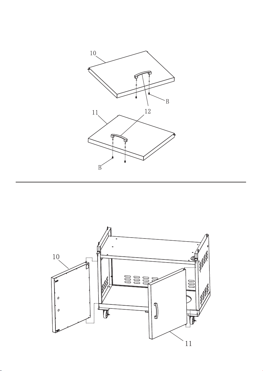
Use 4x M6x12mm screws (B) to attach the door handle (12) to door (10,11).
STEP 6
Attach doors (10,11) to completed cabinet by inserting the bottom door locator into holes, then pressing down on the
top locator insert them into top door locator.
9

988 9
ASSEMBLY INSTRUCTIONS
STEP 7
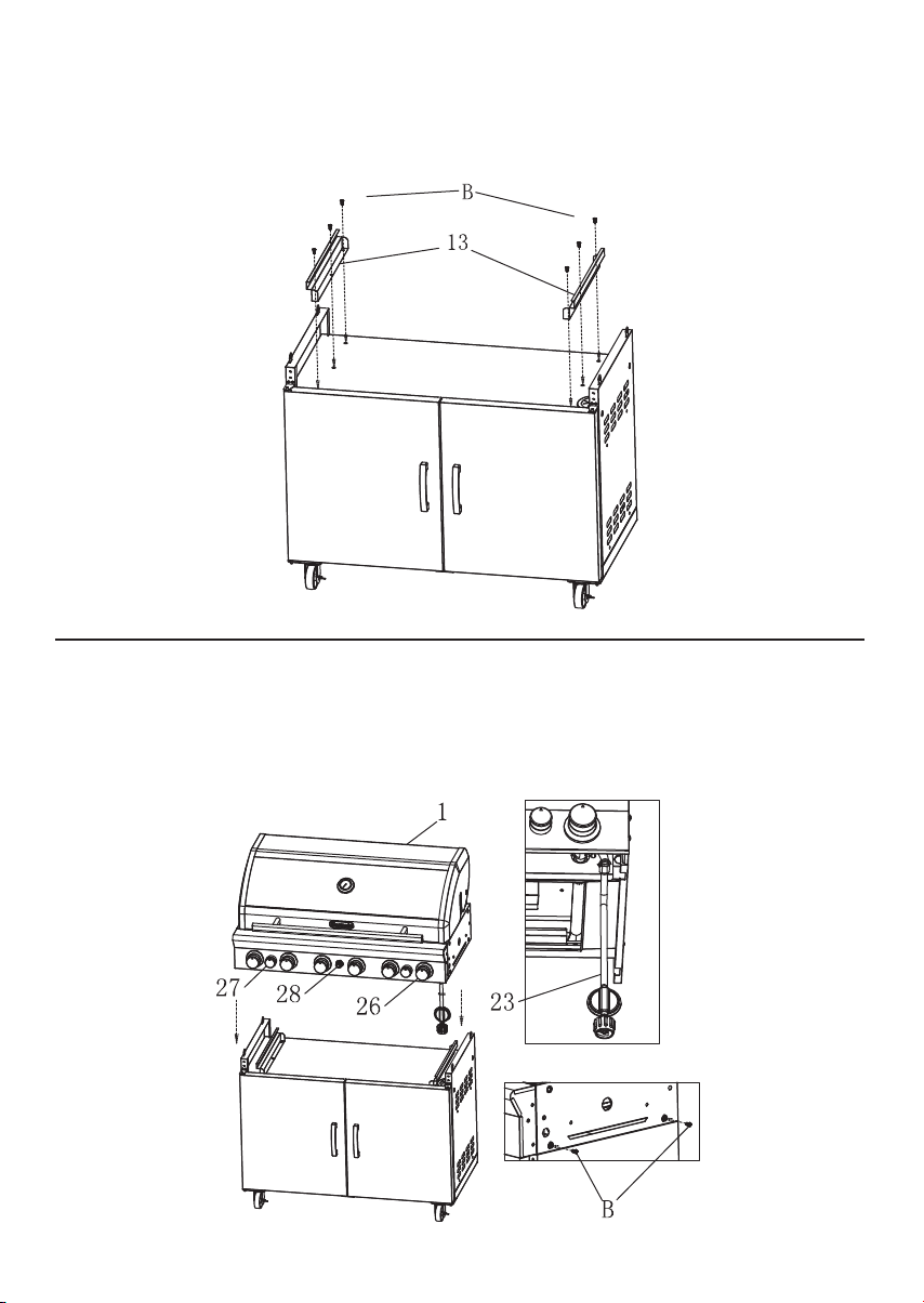
Use 6x M6x12mm screws (B) to attach the flat tray bracket (13) to main cabinet.
STEP 8
Attach hose and gas regulator assembly (23) to firebox assembly (1).
Use 4x M6x12mm screws (B) to attach firebox to the cabinet, making sure that the locators insert into the base of the
firebox (1). Attach the big control knobs (26), small control knobs (27) and ignitor (28).

111010
ASSEMBLY INSTRUCTIONS
STEP 9
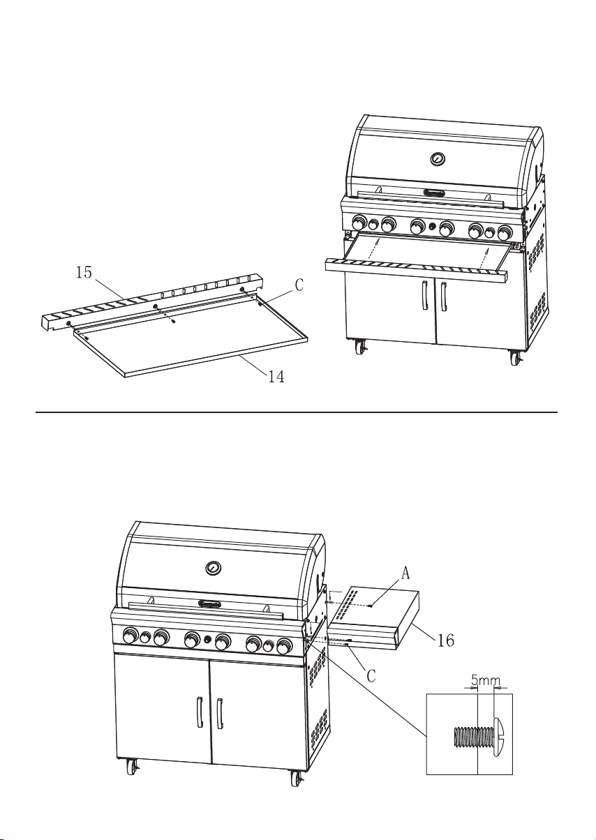
Use 3x M5x12mm screws (C) to attach the flat tray front fascia (15) to the flat tray (14).
STEP 10
Use 4x M6x15mm screws (A) leaving a 5mm gap & 1x M5x12mm screw (C) to attach the R/H side shelf assembly (16)
to the firebox.
Note: DO NOT tighten the bracket now.
11
Ce manuel convient aux modèles suivants
1
Table des matières
Autres manuels Sitro Group Gril