SIRS-E Pilotino WiFi PCB Manuel utilisateur


1. Introduction
2. Safety Information
3. Specification Characteristics
4. Onboard Features (Nomenclature)
5. Mechanical Details
6. Installation
6.1 Access Point Mode Installation
6.1.1 Basic Connection
6.1.2 Daisy Chain
6.2 Station Mode Installation
6.2.1 Basic Connection
6.2.2 Daisy Chain
6.3 Stand Alone Mode Installation
6.3.1 Basic Connection (Access point)
6.3.2 Daisy Chain (Access point)
6.3.3 Basic Connection (Station)
6.3.4 Daisy Chain (Station)
7. WiFi - Access point Mode
7.1 Basic Connection
7.2 Art-Net App Connection
8. WiFi - Station Mode
8.1 Network Connection (WPS)
8.2 IP address
8.3 Art-Net App connection
9. Default Setting
10. Mode LED Indicator
11. Hardware and Accessories
UL Certification
Pg. 3
Pg. 4
Pg. 4
Pg. 5
Pg. 6
Pg. 7
Pg. 8
Pg. 8
Pg. 9
Pg. 10
Pg. 10
Pg. 11
Pg. 12
Pg. 12
Pg. 13
Pg. 14
Pg. 15
Pg. 16
Pg. 16
Pg. 16
Pg. 17
Pg. 17
Pg. 18
Pg. 18
Pg. 19
Pg. 19
Pg. 20
Pg. 21
INDEX
2
3307 West Street Rosenberg, TX 77471 USA - (281) 324-0908
Copyright © 2006-2021 SIRS Electronics Inc. All Rights Reserved PILOTINO WiFi™ PCB Instruction Manual
Updated 09/2021. Rev 2.5
1. Introduction
One of the most important features of this product involves the onboard IO socket. This socket is
meant to be used with the PILOTINO™ PCB with onboard WiFi or capabilities. With the WiFi
module, you instantly convert this PILOTINO™ PCB into an ArtNet node receiving unit. Allowing for
a completely wireless solution.
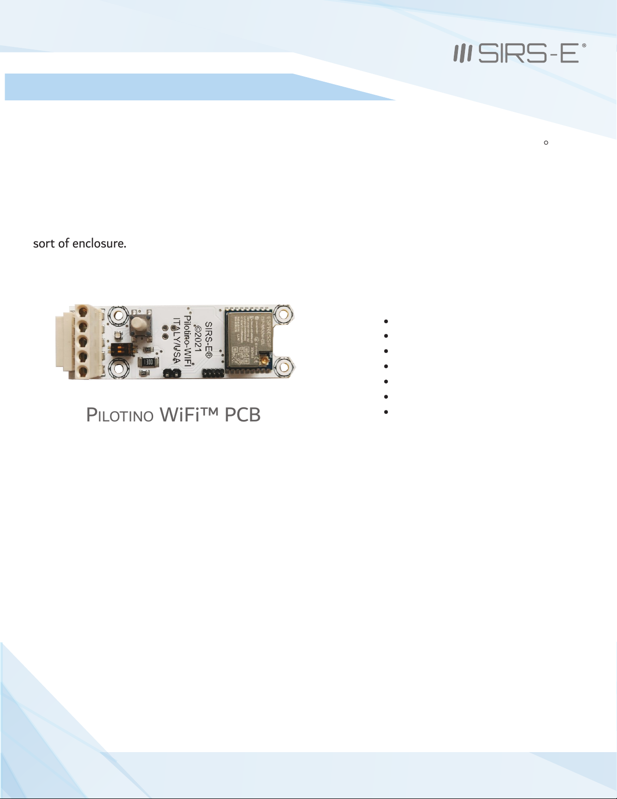
Key Features: PILOTINO WiFi™ PCB
Compatible with any ArtNet App
Robust Wireless 2.4GHz Signal
Standalone WiFi Network
Onboard IO socket for quick integration
Wire to Board Quick Connectors
Plug and Play with Onboard IO Socket
Made in Italy with 5 Year Warranty
The PILOTINO WiFi™ PCB is the newest addition to the LED CV DMX decoder family for SIRS-E. This
version of the PILOTINO™ comes in a bare PCB format. This product is intended to be embedded into
custom fixtures and lighting control systems in which component size is critical. Equipped with four
mounting holes, the PILOTINO WiFi™ PCB is ready to be installed with M2.5 X 5mm stand-offs into any
sort of enclosure.
R
PILOTINO WiFi™ PCB
3
3307 West Street Rosenberg, TX 77471 USA - (281) 324-0908
Copyright © 2006-2021 SIRS Electronics Inc. All Rights Reserved PILOTINO WiFi™ PCB Instruction Manual
Updated 09/2021. Rev 2.5

2. Safety Information
Safety Information
3. Specification Characteristics
The exposed PCB design of this product results in a major reduction in its foot print. With a slim and narrow design, this
configuration is intended to be used in applications that would benefit from this feature. Some examples of applications
include: fixture integration, custom control enclosures, and others. The exposed design comes with few precautions to
take notice of.
The PILOTINO WiFi™ PCB is a non-waterproof device with an IP 20 rating. Keep the unit dry at all times and away from
liquids and humid environments. Make all connections to the power supply, the DMX line and the antenna prior to
powering on the circuit. All lead voltage connections to the drivers must be performed by a licensed electrician. Do not
touch any of the surfaces of the device once the unit is powered on. Ensure that all connections are secure and eliminate
allpossibilities of shorting the unit. Use the proper wire gauge for the wire to board connections. We recommend using
18 awg stranded wire for the power input, and the DMX daisy chain connection. Do not mount the unit where
vibrations or shock are present.
WiFi mode: Station/SoftAP
Security: WPA/WPA2
Encryption: WEP/TKIP/AES
Working Humidity: 0% - 90% non-condensing
IP Rating: IP 20 Non-waterproof (Keep dry)
Ventilation: Do not install in airtight spaces
Software Specification
Min current from supply: 500 mA
Working Voltage: 5V DC
Operating current: 80 mA
Operating temperature: -10 °C to 45 °C
Hardware Specifications
Frequency: 2.4 GHz - 2.5 GHz
Antenna connector: u.FL
4
3307 West Street Rosenberg, TX 77471 USA - (281) 324-0908
Copyright © 2006-2021 SIRS Electronics Inc. All Rights Reserved PILOTINO WiFi™ PCB Instruction Manual
Updated 09/2021. Rev 2.5

4. Onboard Features
1
44
442
3
6
5
7
1. I/O Connection Socket + DMX out (For PILOTINO™ PCB)
2. I/O wire to board quick connectors
3. Dip Switches to set the DMX line termination
4. Mounting holes for Standoffs M2.5 (metric)
5. Pairing button for WiFi connections
6. Mode Indicator LED
7. u.FL connector to connect a receiving Antenna
5
5
3307 West Street Rosenberg, TX 77471 USA - (281) 324-0908
Copyright © 2006-2021 SIRS Electronics Inc. All Rights Reserved PILOTINO WiFi™ PCB Instruction Manual
Updated 09/2021. Rev 2.5

5. Mechanical Details
15.84mm
PILOTINO WiFi™ PCB Top View
22.25mm
68.00mm
16.00mm
49.50mm
16.25mm
PILOTINO WiFi™ PCB Side View
6
3307 West Street Rosenberg, TX 77471 USA - (281) 324-0908
Copyright © 2006-2021 SIRS Electronics Inc. All Rights Reserved PILOTINO WiFi™ PCB Instruction Manual
Updated 09/2021. Rev 2.5

6. Installation
Standoffs
Four 2.5M x 5mm standoffs should be used to properly mount the unit onto a smooth and level surface. It is recommended
that the included factory 2.5M stand offs be used. To fasten the PILOTINO WiFi™ PCB onto a surface, first screw the four
screws in a crisscross pattern. To tighten the screws, torqued them down to ¼ turn past hand tight, again in a crisscross
pattern. Always tighten the screw opposite to the last screw that was torqued down. Do not over tighten the screws as doing
so will result in damage to the device.
Clearance
Due to the exposed contact points on the PILOTINO WiFi™ PCB, the risk of shorting the unit should be considered. A minimum
of 10mm of clearance space is recommended. Never install the PILOTINO WiFi™ PCB within an enclosed space in which the
PILOTINO WiFi™ PCB does not have sufficient space away from other components.
Connections
The PILOTINO WiFi™ PCB comes equipped with wire to board quick connectors, and a socket connector to connect to the
PILOTINO™ PCB . Properly connect the PILOTINO WiFi™ PCB to the PILOTINO™ PCB with the boards facing the same direction.
All wire connections should fit securely into the connectors. Be sure to insert each wire into the connectors deep enough so
that no bare wire is exposed. A good rule of thumb is to strip the wires so that only about 3mm of insulation is removed.
To have the best network connection, place the PILOTINO WiFi™ PCB in a location where the antenna has a clear line of
sight from the device connected to.
7
3307 West Street Rosenberg, TX 77471 USA - (281) 324-0908
Copyright © 2006-2021 SIRS Electronics Inc. All Rights Reserved PILOTINO WiFi™ PCB Instruction Manual
Updated 09/2021. Rev 2.5

6.1 Access Point Mode Installation
6.1.1 Basic Connection
Make sure the PILOTINO WiFi™ PCB and antenna are connected to the PILOTINO™ PCB.
Power on the PILOTINO™ PCB board once proper wiring connections are done to eliminate
short circuiting the board.
With the smartphone device, go to the “Settings -> WiFi/Network -> PilotWiFi_####, where #### is a
random sequence of four numbers.
When first prompted for a password, type PilotWiFi_0000.
Use any Art-Net IOS or Android App to drive the PILOTINO™ PCB.
8
3307 West Street Rosenberg, TX 77471 USA - (281) 324-0908
Copyright © 2006-2021 SIRS Electronics Inc. All Rights Reserved PILOTINO WiFi™ PCB Instruction Manual
Updated 09/2021. Rev 2.5

6.1 Access Point Mode Installation
6.1.2 Daisy Chain
Make sure the PILOTINO WiFi™ PCB and antenna are connected to the PILOTINO™ PCB.
Connect the DMX IN/OUT wires to each of the PILOTINO™ PCB boards in a sequence, similar
to a daisy flower ring, to each corresponding connector.
Power on the PILOTINO™ PCB boards once proper wiring connections are done to eliminate
short circuiting the boards.
With the smartphone device, go to the “Settings -> WiFi/Network -> PilotWiFi_####, where #### is a
random sequence of four numbers.
When first prompted for a password, type PilotWiFi_0000.
Use any Art-Net iOS or Android App to drive the PILOTINO™ PCB.
9
3307 West Street Rosenberg, TX 77471 USA - (281) 324-0908
Copyright © 2006-2021 SIRS Electronics Inc. All Rights Reserved PILOTINO WiFi™ PCB Instruction Manual
Updated 09/2021. Rev 2.5
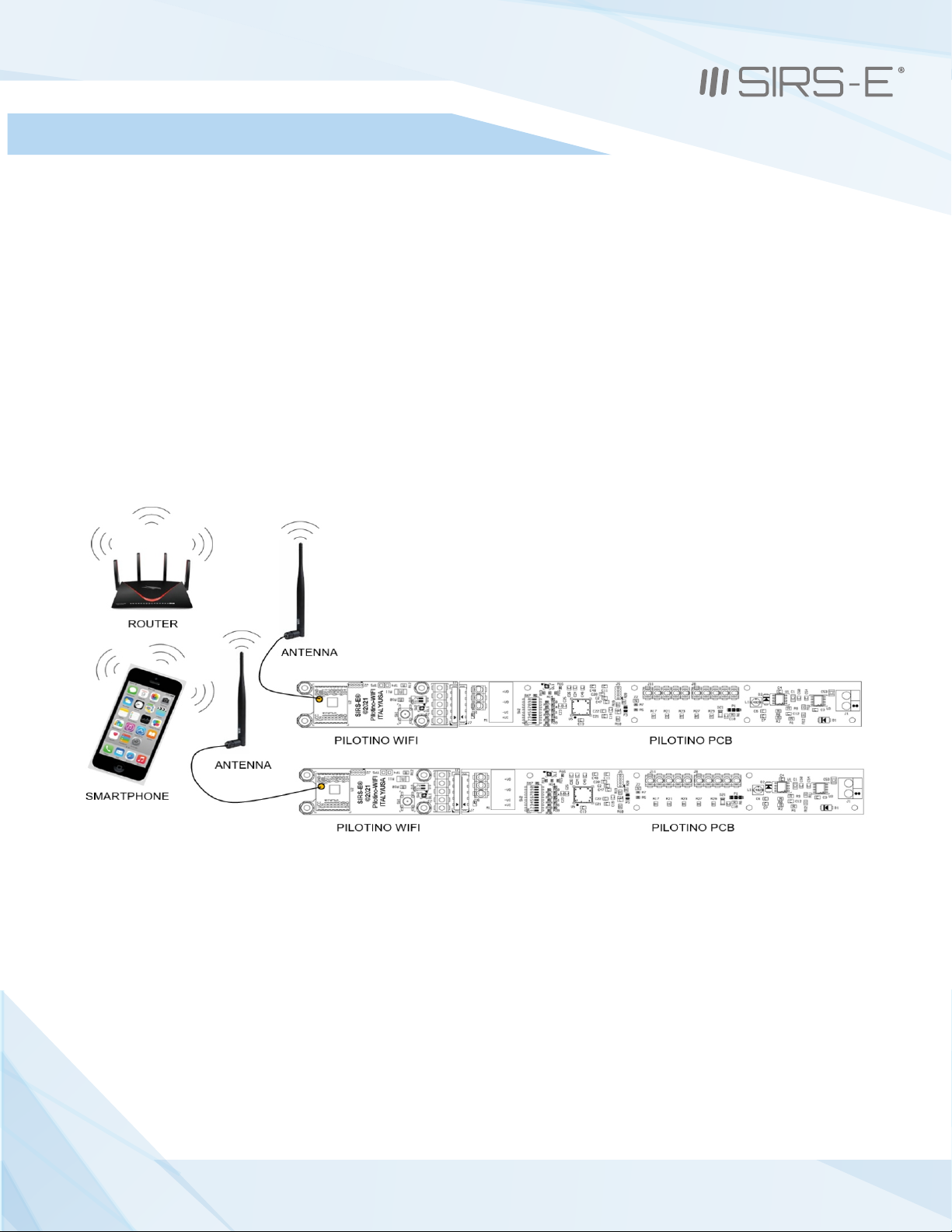
6.2 Station Mode Installation
6.2.1 Basic Connection
Make sure when connecting each PILOTINO WiFi™ PCB and antenna to a PILOTINO™ PCB.
Power on the PILOTINO™ PCB boards once proper wiring connections are done to eliminate
short circuiting the boards.
Connect the PILOTINO WiFi™ PCB to a router by a WPS procedure (for more details see chapter 8.1).
Also, connect the smartphone to the router and use any Art-Net iOS or Android App to drive each
PILOTINO™ PCB.
10
PILOTINO WiFi™ PCB Instruction Manual
Updated 09/2021. Rev 2.5
3307 West Street Rosenberg, TX 77471 USA - (281) 324-0908
Copyright © 2006-2021 SIRS Electronics Inc. All Rights Reserved
Autres manuels pour Pilotino WiFi PCB
1
Table des matières
Autres manuels SIRS-E Équipement d'éclairage

Manuels Équipement d'éclairage populaires d'autres marques


Qazqa
Qazqa Suplux SL 3 Black 103062 Manuel utilisateur

Commercial Electric
Commercial Electric 54568141 Manuel utilisateur

CREE LIGHTING
CREE LIGHTING 304 Series Manuel utilisateur

Goobay
Goobay 49867 Manuel utilisateur

ECOMAN ITALIA
ECOMAN ITALIA LED T8 Manuel utilisateur

Alkalite
Alkalite Krypton KT-81 Manuel utilisateur


