Sinovo SD95H Series Manuel utilisateur

1
Preface
Contents
Chapter 1 Safety and Cautions.........................................................................2
Chapter 2 Product Information.........................................................................9
Chapter 3 Operation And Display...................................................................16
Chapter 4 Function Parameters Table...........................................................19
Chapter 5 Troubleshooting ............................................................................44
Chapter 6 RS485 Communication Protocol..................................................48
Thank you for purchasing the SD95H series AC drive developed by Our
company.For the users who use this product for the first time, read the manual
carefully.
5. In general , the warranty card will not be re-issued. Please keep the card and
present it to the maintenance personnel when asking for maintenance .
6. If there is any problem during the service , please contact the agent of our
company or our company directly .
The damage or failure caused by the trouble out of the equipment (e.g. :
External device)
7. The company reserves the right to interpret this agreement
2. Within the warranty period , maintenance will be charged for the damages
caused by the following reasons :
3. If there is any failure or damage to the product, please fill in the information
of the Product Warranty Card in details correctly.
The damage caused by improper use or repair/modification without prior
permission.
The damage caused by fire , flood , abnormal voltage , other natural
disasters and second disaster.
4. The maintenance fee is charged according to the newly adjusted
Maintenance Price List of our company .
The damage caused by the improper operation.
1. The warranty period of the product is 18 months (refer to the bar code on the
equipment body). During the warranty period , if the product fails or damaged
under the condition of normal use by following the instruction, we will be
responsible for free maintenance.
The hardware damage caused by artificial falling or transportation after
purchase.
Warranty Agreement
2
Chapter 1 Safety and Cautions
Safety and Cautions Definition
Read this manual carefully so that you have a thorough understanding.
Installation, commissioning or maintenance may be performed in conjunction
with this chapter. Our company will assume no ability and responsibility for any
injury or loss caused by improper operation.
Danger
Note
Indicates that failure to comply with the notice will result in severe personal
injury or even death.
Indicates that failure to comply with the notice will result in personal injury or
property damage.
1.1 Safety Cautions
Use Stage Safety Grade Precautions
Danger
Before
Installation
tDo not install the equipment if you find water seepage,
component missing or damage upon unpacking.
tDo not install the equipment if the packing list does not
conform to the product you received.
Danger
tHandle the equipment with care during transportation
to prevent damage to the equipment.
tDo not use the equipment if any component is
damaged or missing. Failure to comply will result in
personal injury.
tDo not touch the components with your hands. Failure
to comply will result in static electricity damage.
3
Safety and Cautions
Use Stage Safety Grade Precautions
During
Installation
Note
Danger
t Install the equipment on incombustible objects such
as metal, and keep it away from combustible
materials. Failures to comply may result in a fire.
t Do not loosen the fixed screws of the components,
especially the screws withe red marks.
t Do not drop wire end or screw into the AC drive.
Failure it will result in damage to the AC drive.
t arrange the installation positions properly to ensure
the cooling effect.
t When two AC drives are laid in the same cabinet ,
t Install the AC drive in places free of vibration and
direct sunlight.
Danger
tA circuit breaker must be used to isolate the power
supply and the AC drive. Failure to comply may result
a fire.
tEnsure that the power supply is cut off before wiring.
Failure to comply may result in electric shock.
tNever connect the power cables to the output
terminals(U,V,W) of the AC drive. Pay attention to the
marks of the wiring terminals and ensure correct
wiring. Failure to comply may result in damage to the
AC drive.
t Never connect the power cables the braking resistor
between the DC bus terminals P+, P-. Failure to
comply may result in a fire.
tEnsure that the main cable line comply with the
standard, the line meets the EMC requirements and
the area safety standard. Failure to comply may result
in risk or accident.
tUse a shielded cable for the encoder, and ensure that
the shielding layer is reliably grounded.
At wiring
4
Use Stage Safety Grade Precautions
Danger
tPlease confirm the peripheral equipment and cable
converter is configured in this manual of the
recommended model, all the configuration line in
accordance with the connection method of the
manual provides the correct wiring. Failure to comply
will result in accidents.
tCheck that the voltage class of the power supply is
consistent with the rated voltage class of the AC
drive.
Before
Power-on
Danger
After
Power-on
tDo not open the AC drive’s cover after power-on.
Failure to comply may result in electric shock.
tDo not change the default settings of the AC drive.
Failure to comply will result in damage to the AC drive.
tDo not touch the operation of AC drive during the
hands is wet. Failure to comply will result in accident.
tDo not touch any I/O terminal of the AC drive. Failure
to comply may result in electric shock.
tDo not touch the rotating part of the motor during the
motor auto-tuning or running. Failure to comply will
result in accident.
Danger
During
Operation
tSignal detection must be performed only by qualified
personnel during operation. Failure to comply will
result in personal injury or damage to the AC drive.
tDo not touch the fan or the discharging resistor to
check the temperature. Failure to comply will result in
personal burnt.
Danger
tAvoid objects falling into the AC drive when it is
running. Failure to comply will result in damage to the
AC drive.
tDo not start or stop the AC drive by turning the
contactor ON/OFF. Failure to comply will result in
damage to the AC drive.
Safety and Cautions
5
Use Stage Safety Grade Precautions
Danger
tDo not repair or maintain the AC drive at power-on.
Failure to comply will result in electric shock.
tEnsure that the AC drive is disconnected from all
power suppliers before staring repair or maintenance
on the AC drive.
During
Maint-
enance
Danger
tRepair or maintenance of the AC drive may be
performed only by qualified personnel. Failure to
comply will result in personal injury or damage to the
AC drive.
tSet and check the parameters again after the AC drive
is replaced.
During
Maint-
enance
1.2 Cautions
1.2.1 Motor Insulation Test
Perform the insulation test when the motor is used for the first time, or when it is
reused after being stored for a long time, or in a regular check-up, in order to
prevent the poor insulation of motor windings from damaging the AC drive
during the insulation test. A 500-V mega-Ohm meter is recommended for the
test. The insulation resistance must not be less than 5MΩ.
1.2.2 Thermal Protection of Motor
If the selected AC drive does not match the rated capacity of the motor ,
especially when the rated power of the AC drive is higher than that of the motor,
adjust the parameters for motor protection in the AC drive or to install thermal
relay to protect the motor .
1.2.3 Running Below and Above Rated Frequency
The AC drive provides frequency output of 0 to 600.00Hz. When the users use
the frequency converter for a long time, please pay attention to the motor
cooling or use of variable frequency motor. If the AC drive is required to run at
over 50Hz, consider the capacity of the machine.
Safety and Cautions

6
1.2.4 Motor heat and noise
The output of the AC drive is pulse width modulation (PWM) wave with certain
harmonic frequencies, and therefore, the motor temperature, noise, and
vibration are slightly greater than those when the AC drive runs at power
frequency (50Hz).
1.2.5 Voltage-sensitive device or capacitor on output side of the AC drive
Do not install the capacitor for improving power factor or lightning protection
voltage sensitive resistor on the output side of the AC drive because the output
of the AC drive is PWM wave. Otherwise, the AC drive may suffer transient
overcurrent or even be damaged.
1.2.6 Contactor at the I/O terminal of the AC drive
When a contactor is installed between the input side of the AC drive and the
power supply, the AC drive must not be started or stopped by switching the
contactor on or off. If the AC drive has to be operated by the contactor, ensure
that the time interval between switching is at least one hour since frequent
charge and discharge will shorten the service life of the capacitor inside the
AC drive.
When a contactor is installed between the output side of the AC drive and the
motor,do not turn off the contactor when the AC drive is active. Otherwise,
modules inside theAC drive may be damaged.
1.2.7 When External Voltage is Out of Rated Voltage Range
The AC drive must not be used outside the allowable voltage range specified in
this manual. Otherwise, the AC drive may be damaged . If required, use a
corresponding voltage step-up or step-down device.
Safety and Cautions

7
1.2.8 The Derating of the AC Drive
Different power grade frequency converter has its default carrier frequency,
when to run at a higher carrier.frequency, the AC Drive must to reduce the
amount when running.
1.2.9 Prohibition of Three-Phase Input Change into Two-Phase Input
Do not change the three-phase input of the AC drive into two-phase input.
Otherwise, a fault will result or the AC drive will be damaged.
1.2.10 Surge Suppressor
The AC drive has a built-in over-voltage, over-current device for suppressing the
surge voltage generated when the inductive loads around the AC drive are
switched on or off. If the inductive loads generate a very high surge voltage, use
a surge suppressor for the inductive load to prolong the service life of the AC
drive.
1.2.11 Ambient Temperature and De-rating
The normal use of the frequency converter ambient temperature is -10℃~40℃.
Temperature exceeds 40℃,the equipment need to reduce the amount of use.
The ambient temperature of each increase is reduced by 1.5%,the maximum
use of the ambient temperature is 50℃.
1.2.12 Altitude and De-rating
In places where the altitude is above 1000m and the cooling effect reduces due
to thin air, it is necessary to de-rate the AC drive. Contact our company for
technical support.
1.2.13 Disposal
The electrolytic capacitors, plastic parts and other devices may explode when
they are burnt. Poisonous gas is generated when they are burnt. Treat them as
ordinary industrial waste according to relevant national laws and regulations.
Safety and Cautions

8
1.2.14 Adaptable Motor
tThe cooling fan and rotor shaft of general motor are coaxial, which results in
reduced cooling effect when the rotational speed declines. If variable speed is
required, add a more powerful fan or replace it with variable-frequency motor
in applications where the motor runs at low frequency for a long time.
t The standard parameters of the adaptable motor have been configured
inside the AC drive. It is still necessary to perform motor auto-tuning or modify
the default values based on actual conditions. Otherwise, the running effect
and protection performance will be affected.
tThe standard adaptable motor is adaptable four-polo squirrel-cage AC
asynchronous induction motor or PMSM. For other types of motor, select a
proper AC drive according to the rated motor current.
tThe AC drive may alarm or even be damaged when short-circuit exists on
cables or inside the motor. Therefore, perform insulation short-circuit test
when the motor and cables are newly installed or during routine maintenance.
During the test, make sure that the AC drive is disconnected from the tested
parts.
Safety and Cautions
9
Chapter 2 Product Information
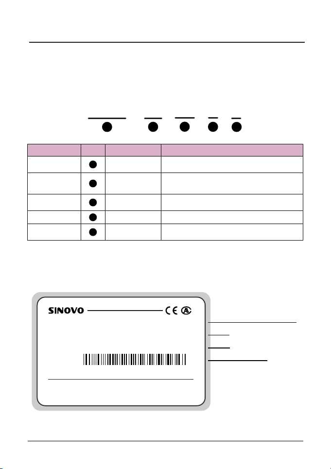
2.1 Naming Rules
Model code contains product information. Users can find the code on the model
designation label attached to the AC drive or the simple nameplate.
-
SD95H
1
4T
2
G
4
5.5
3
C
5
Fig. 2-1 Name Designation Rules
SD95H series
1
2
4
3
5
Name Mark Description Detail
AC drive
series
Voltage
level
Adaptable
power
Load type
Braking
unit mark
Voltage level
Adaptable motor
power(KW)
Load type
Braking unit
Sinodrive95H abbreviates Sd95H
2S: Single-phase 220V Range:-15%~20%
4T: Three-phase 380V Range:-15%~20%
Null: None
C: With a brake unit
0.7KW~55.0KW
G: General type
2.2 Nameplate
Fig. 2-2 Product nameplate
SHENZHEN SINOVO ELECTRIC TECHNOLOGIES CO.,LTD.
MODEL: SD95H-4T-5.5G
INPUT: AC3PH 380V 50/60Hz 14.6A
OUTPUT: AC3PH 380V 0~2000Hz 13.0A
S/N: FDLAGCA0A040
MADE IN CHINA
The AC drive model
Rated input voltage,
frequency and current
Bar code
Rated output voltage,
frequency and current
10
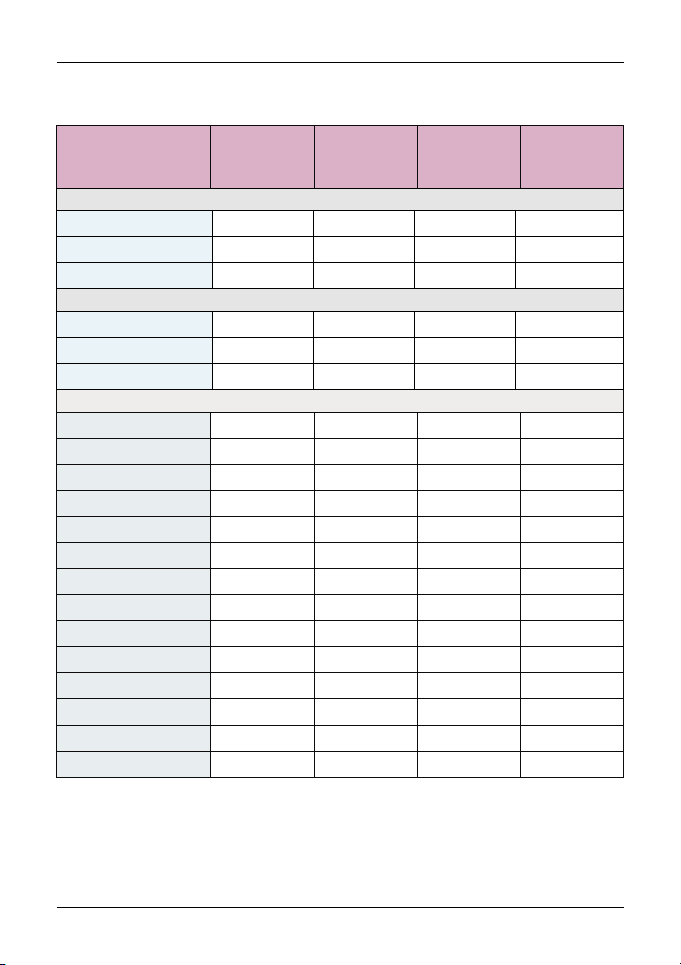
2.3 SD95H Series AC Drive
Product Information
Model
Power
Capacity
(KVA)
Input
Current
(A)
Output
Current
(A)
Adaptable
Motor
(KW)
Three-phase 380V Range:-15%~20%
1.5 3.4 0.752.3 0.75
3.0
4.0
5.9
8.9
11
40
57
69
85
17
21
24
30
5.0 3.7 1.5
5.8 5.1 2.2
10.5 8.5 4.0
14.6 13 5.5
20.5 17 7.5
62.5 60 30
76.0 75 37
92.0 91 45
113 112 55
26.0 25 11
35.0 32 15
38.5 37 18.5
46.5 45 22
SD95H-4T-55G
SD95H-4T-0.7G
SD95H-4T-1.5G
SD95H-4T-2.2G
SD95H-4T-4.0G
SD95H-4T-5.5G
SD95H-4T-7.5G
SD95H-4T-11G
SD95H-4T-15G
SD95H-4T-18.5G
SD95H-4T-22G
SD95H-4T-30G
SD95H-4T-37G
SD95H-4T-45G
1.5 8.2 0.754.7 0.75
3.0
4.0
14.0 7.5 1.5
23.0 10.0 2.2
SD95H-2S-0.7G
SD95H-2S-1.5G
SD95H-2S-2.2G
1.5 5.5 0.754.7 0.75
3.0
4.0
7.7 7.5 1.5
12.0 10.0 2.2
SD95H-2T-0.7G
SD95H-2T-1.5G
SD95H-2T-2.2G
Single-phase 220V Range:-15%~20%
Three-phase 220V Range:-15%~20%
Ce manuel convient aux modèles suivants
17
Table des matières
Manuels Entraînement CC populaires d'autres marques

Vincent Associates
Vincent Associates UNIBLITZ ED12DSS Manuel utilisateur

EKSMA OPTICS
EKSMA OPTICS DQ-100-4 Manuel de la liste des pièces

Chamberlain Garog
Chamberlain Garog D Series Manuel utilisateur

Parker
Parker PDS Series Manuel utilisateur

Festo
Festo DGC G Series Guide de configuration

Binks
Binks QS-5012-1-CE Manuel utilisateur


