SL-881 6G Handheld HDMI/MHL Audio and Video Generator/Analyzer
User Guide
Simplay-UG-02001-E © 2016-2017 Simplay Labs, LLC., 3
All rights reserved. CONFIDENTIAL
Figures
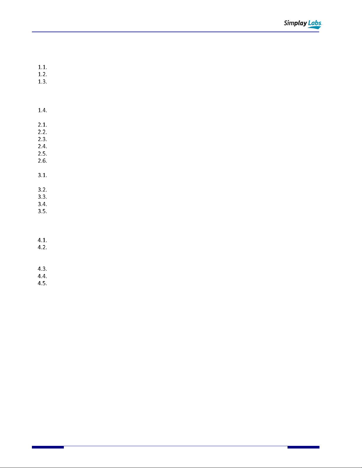
Figure 1.1. SL-881 AVG − Top View.......................................................................................................................................5
Figure 1.2. SL-881 AVG − Front Panel ...................................................................................................................................5
Figure 1.3. SL-881 AVG − Rear Panel ....................................................................................................................................6
Figure 1.4. Locating SL-881 AVG Components − Top View...................................................................................................6
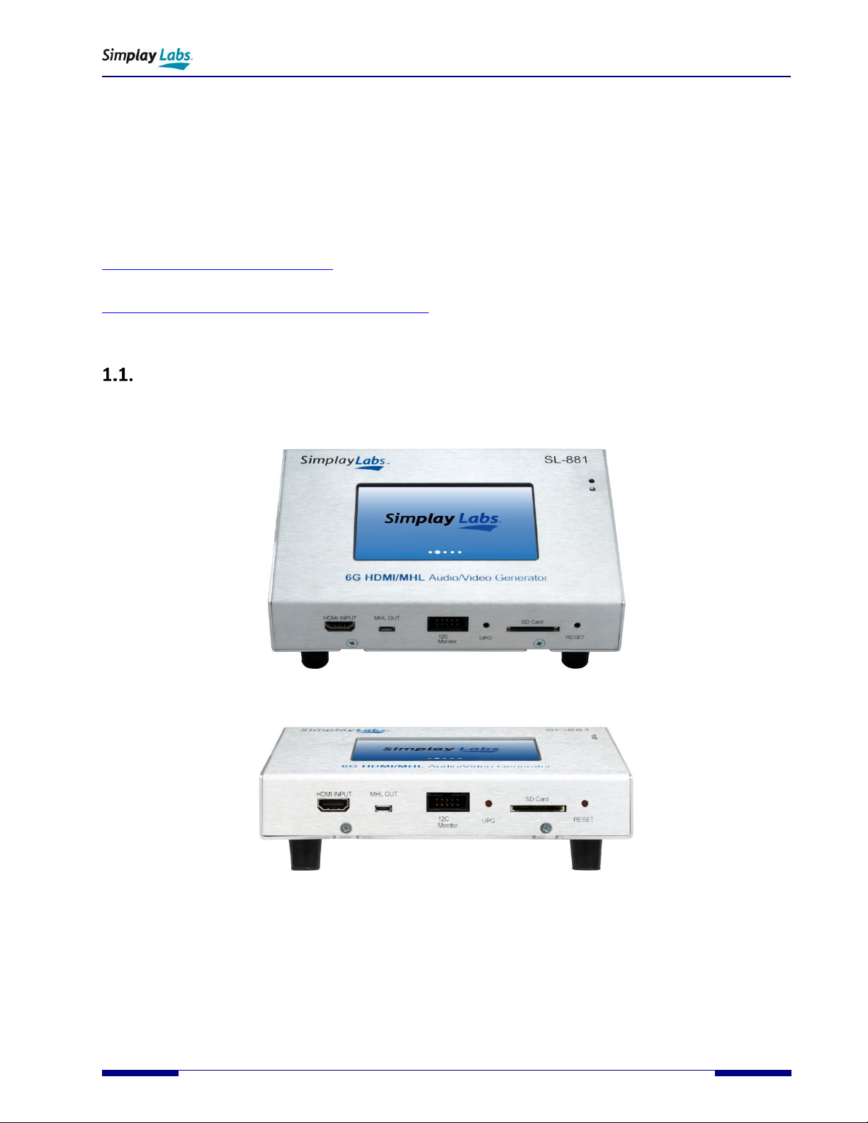
Figure 1.5. LCD Touch Screen Main Window........................................................................................................................8
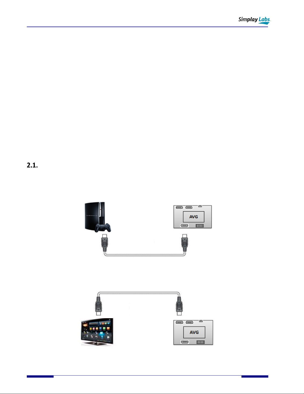
Figure 2.1. Connecting with HDMI Source Device in Stand-alone Mode ...........................................................................10
Figure 2.2. Connecting with HDMI Sink Device in Stand-alone Mode................................................................................10
Figure 2.3. Connecting with MHL Source Device in Stand-alone Mode .............................................................................11
Figure 2.4. Connecting with MHL Sink Device in Stand-alone Mode..................................................................................11
Figure 2.5. Video Generator Window.................................................................................................................................12
Figure 2.6. Video Analyzer Window....................................................................................................................................13
Figure 2.7. Read EDID from Sink DUT Window...................................................................................................................14
Figure 2.8. Load EDID to Sink TE Window...........................................................................................................................15
Figure 2.9. Factory Test Window ........................................................................................................................................16
Figure 3.1. Inside the Software Package.............................................................................................................................17
Figure 3.2. Install the VCP Driver ........................................................................................................................................18
Figure 3.3. Install the Dpinst Driver ....................................................................................................................................18
Figure 3.4. The SL-881 AVG Shown in Device Manager......................................................................................................18
Figure 3.5. Locate and Open Setup.exe ..............................................................................................................................19
Figure 3.6. Welcome to the AVG Setup Wizard..................................................................................................................19
Figure 3.7. AVG Application Shortcut .................................................................................................................................19
Figure 3.8. AVG Software Main Window on Test Computer ..............................................................................................20
Figure 3.9. Connect Device Dialog ......................................................................................................................................20
Figure 3.10. No License File Found Dialog ..........................................................................................................................20
Figure 3.11. License Manager Dialog..................................................................................................................................21
Figure 3.12. The Windows Save As Dialog..........................................................................................................................21
Figure 3.13. Send by Email Dialog.......................................................................................................................................21
Figure 3.14. License Requirement File to Simplay Labs......................................................................................................22
Figure 3.15. License Menu Item Enabled............................................................................................................................23
Figure 3.16. Options Enabled in AVG Software Main Window...........................................................................................23
Figure 4.1. EDDC (SCDC) Compliance Test Windows ..........................................................................................................24
Figure 4.2. CdfSource and CdfSink Dialogs .........................................................................................................................25
Figure 4.3. Instruction Dialogs ............................................................................................................................................25
Figure 4.4. EDDC Source Test with Log File ........................................................................................................................26
Figure 4.5. EDDC Sink Test with Log File.............................................................................................................................26
Figure 4.6. HDR Palette Window ........................................................................................................................................27
Figure 4.7. DDC Waveform Viewer .....................................................................................................................................28
Figure 4.8. Sample DDC Waveform ....................................................................................................................................28
Figure 4.9. Sample Test Report...........................................................................................................................................29
Figure 4.10. Cable Loop-back Test Windows ......................................................................................................................30
Figure 4.11. Selected Items in Test List ..............................................................................................................................30
Figure 4.12. Cable DUT Test Setup .....................................................................................................................................31
Figure 4.13. Cable Loop Test in the Single Mode ...............................................................................................................31
Figure 4.14. Sample Test Report.........................................................................................................................................32
Figure 4.15. Cable Loop Test in the Batch Mode ................................................................................................................33
Figure 4.16. Cable Loop Test - Detailed Result Area...........................................................................................................33
Figure 4.17. DDC Monitor Test Window.............................................................................................................................34
Figure 4.18. Input Port Monitor Instruction Dialog ............................................................................................................34
Figure 4.19. Output Port Monitor Instruction Dialog .........................................................................................................35
Figure 4.20. Pass Through Monitor Instruction Dialog .......................................................................................................35
Figure 4.21. DDC Monitor Activities Window.....................................................................................................................36
Figure 4.22. DDC Log Filter .................................................................................................................................................37