SimCom SIM7500 Series Manuel utilisateur
SIM7500_EVB Kit_User Guide_V1.01

Smart Machine Smart Decision
SIM7500_EVB Kit_User Guide_V1.01 22017-12-12
Document Title:
SIM7500_EVB Kit_User Guide
Version:
1.01
Date:
2017-12-12
Status:
Release
Document Control ID:
SIM7500_EVB Kit_User Guide_V1.01
General Notes
SIMCom offers this information as a service to its customers, to support application and engineering efforts
that use the products designed by SIMCom. The information provided is based upon requirements
specifically provided to SIMCom by the customers. SIMCom has not undertaken any independent search for
additional relevant information, including any information that may be in the customer’s possession.
Furthermore, system validation of this product designed by SIMCom within a larger electronic system
remains the responsibility of the customer or the customer’s system integrator. All specifications supplied
herein are subject to change.
Copyright
This document contains proprietary technical information which is the property of SIMCom Limited.,
copying of this document and giving it to others and the using or communication of the contents thereof, are
forbidden without express authority. Offenders are liable to the payment of damages. All rights reserved in
the event of grant of a patent or the registration of a utility model or design. All specification supplied herein
are subject to change without notice at any time.
Copyright © Shanghai SIMCom Wireless Solutions Ltd. 2016

Smart Machine Smart Decision
SIM7500_EVB Kit_User Guide_V1.01 32017-12-12
Contents
Contents..................................................................................................................................................................... 3
Version History.......................................................................................................................................................... 5
1. SIMCOM-EVB overview...................................................................................................................................... 6
2. EVB Accessory...................................................................................................................................................... 8
3. Accessory Interface................................................................................................................................................ 9
3.1 Power Interface............................................................................................................................................ 9
3.2 Audio Interface ............................................................................................................................................ 9
3.3 SIM card interface....................................................................................................................................... 9
3.4 USB Interface ............................................................................................................................................ 10
3.5 Power switch.............................................................................................................................................. 10
3.6 POWER_ON Button.................................................................................................................................. 10
3.7 RF switch................................................................................................................................................... 10
3.8 LED Indicator.............................................................................................................................................11
4. Test Interface ........................................................................................................................................................11
4.1 Test Point A.................................................................................................................................................11
4.2 Test Point B................................................................................................................................................ 12
4.3 Test Point C................................................................................................................................................ 13
4.4 Test Point D ............................................................................................................................................... 14
4.5 Test Point E................................................................................................................................................ 15
5. Illustration............................................................................................................................................................ 16
5.1 SIMCom TE installation and uninstallation .............................................................................................. 16
5.2 Power on module:...................................................................................................................................... 16
5.3 AT communication..................................................................................................................................... 17

Smart Machine Smart Decision
SIM7500_EVB Kit_User Guide_V1.01 42017-12-12
Figure Index
FIGURE1: SIMCOM-EVB TOP VIEW.............................................................................................................................6
FIGURE2: SIMCOM-EVB BOTTOM VIEW ...................................................................................................................7
FIGURE 3: EVB ACCESSORY.........................................................................................................................................8
FIGURE4: AUDIO INTERFACE.......................................................................................................................................9
FIGURE 5: VIRTUAL SERIAL PORT............................................................................................................................10
FIGURE 6: RF SWITCH..................................................................................................................................................10
FIGURE 7: TEST INTERFACE OVERVIEW................................................................................................................. 11
FIGURE 8:TEST POINT A.............................................................................................................................................. 11
FIGURE9: TEST POINT B..............................................................................................................................................12
FIGURE10: TEST POINT C............................................................................................................................................13
FIGURE11: TEST POINT D............................................................................................................................................14
FIGURE12: TEST POINT E ............................................................................................................................................15
FIGURE13: TE ASSEMBLY ...........................................................................................................................................16

Smart Machine Smart Decision
SIM7500_EVB Kit_User Guide_V1.01 52017-12-12
Version History
Data
Version
Description of change
Author
2016-07-12
1.00
Origin
shijie.yuan
2017-12-12
1.01
modification
Albert Meng
SCOPE
This document describes how to use SIMCOM-EVB to do test; user can get useful info about the SIMCOM-EVB
quickly through this document.
This document is subject to change without notice at any time.
Smart Machine Smart Decision
SIM7500_EVB Kit_User Guide_V1.01 62017-12-12
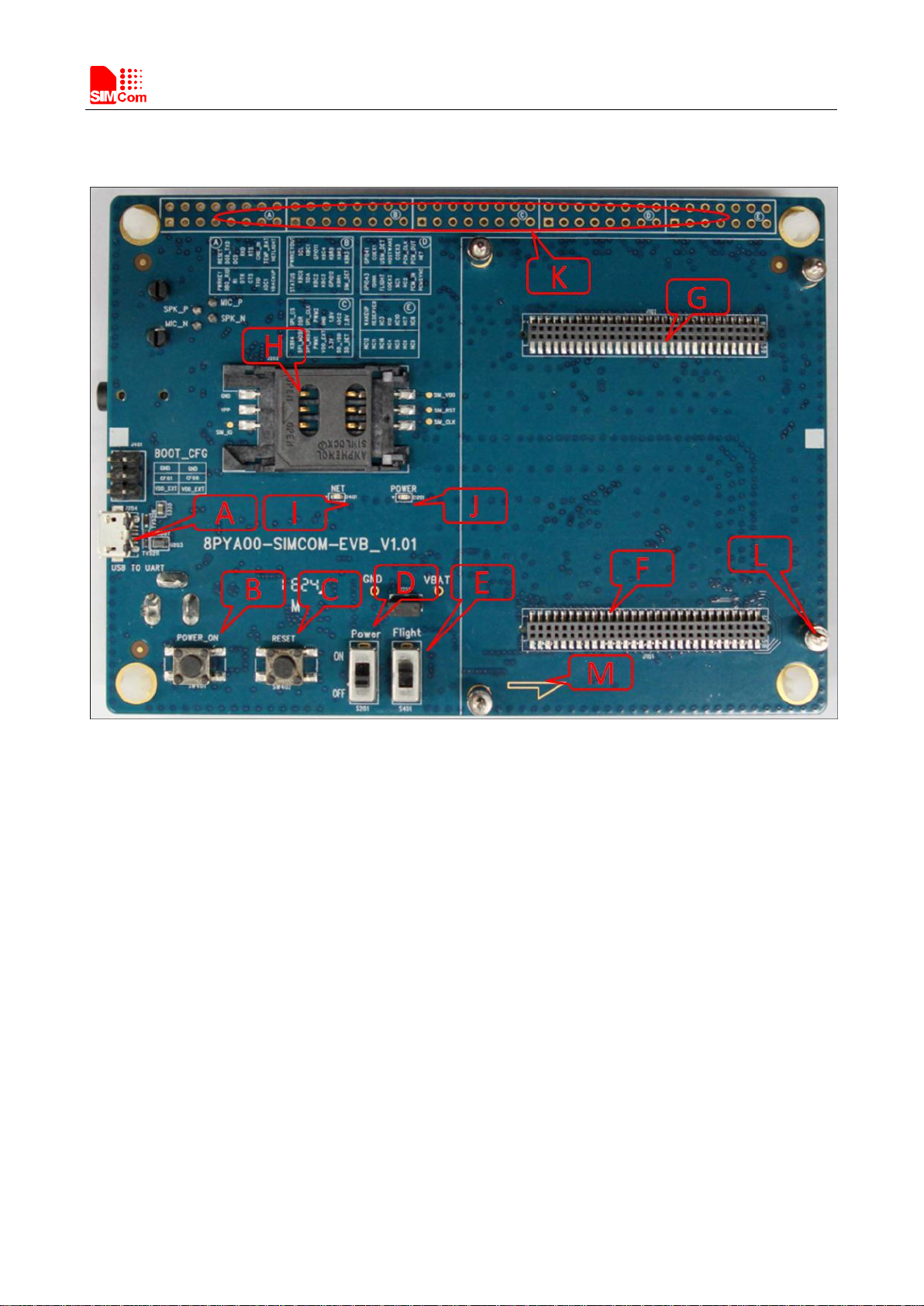
1. SIMCOM-EVB overview
Figure1: SIMCOM-EVB TOP view
Smart Machine Smart Decision
SIM7500_EVB Kit_User Guide_V1.01 72017-12-12
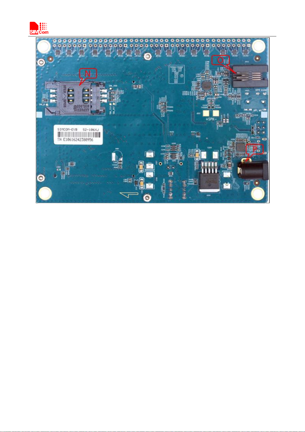
Figure2: SIMCOM-EVB BOTTOM view
A: USB jack
B: Powerkey
C: Reset
D: Power switch
E: RF switch
F: TE connector
G: TE connector
H: Main SIMcard holder
I: LED indicator for Netlight
J: LED indicator for Power
K: Test Point
L: Studs and nuts
M: mark of TE Module direction
N: Second SIM card holder
O: Handset jack
P: Power jack
Smart Machine Smart Decision
SIM7500_EVB Kit_User Guide_V1.01 82017-12-12
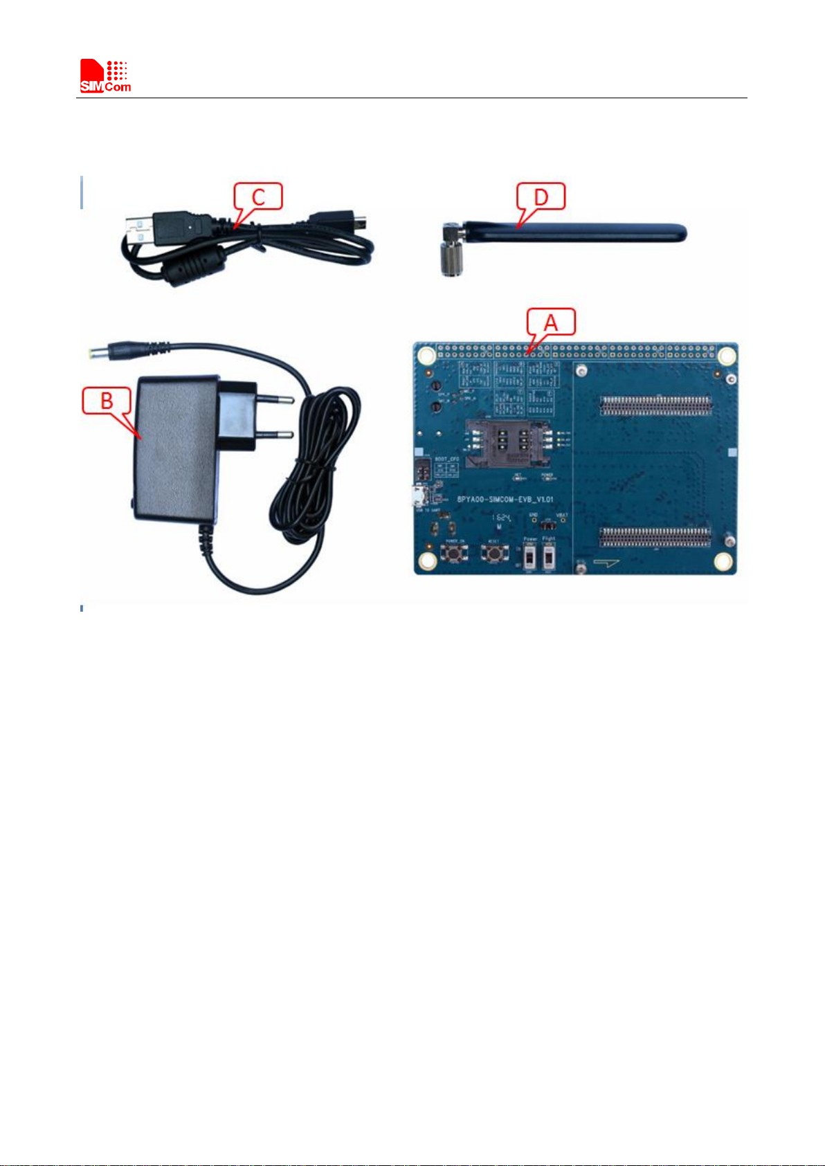
2. EVB Accessory
Figure 3: EVB Accessory
A: SIMCOM-EVB
B: 5V DC adapter
C: USB Cable
D: GSM/WCDMA /LTE antenna
Smart Machine Smart Decision
SIM7500_EVB Kit_User Guide_V1.01 92017-12-12
3. Accessory Interface
3.1 Power Interface
Pin
Signal
I/O
Description
1
Adapter input
I
5V/2.0A DC source input
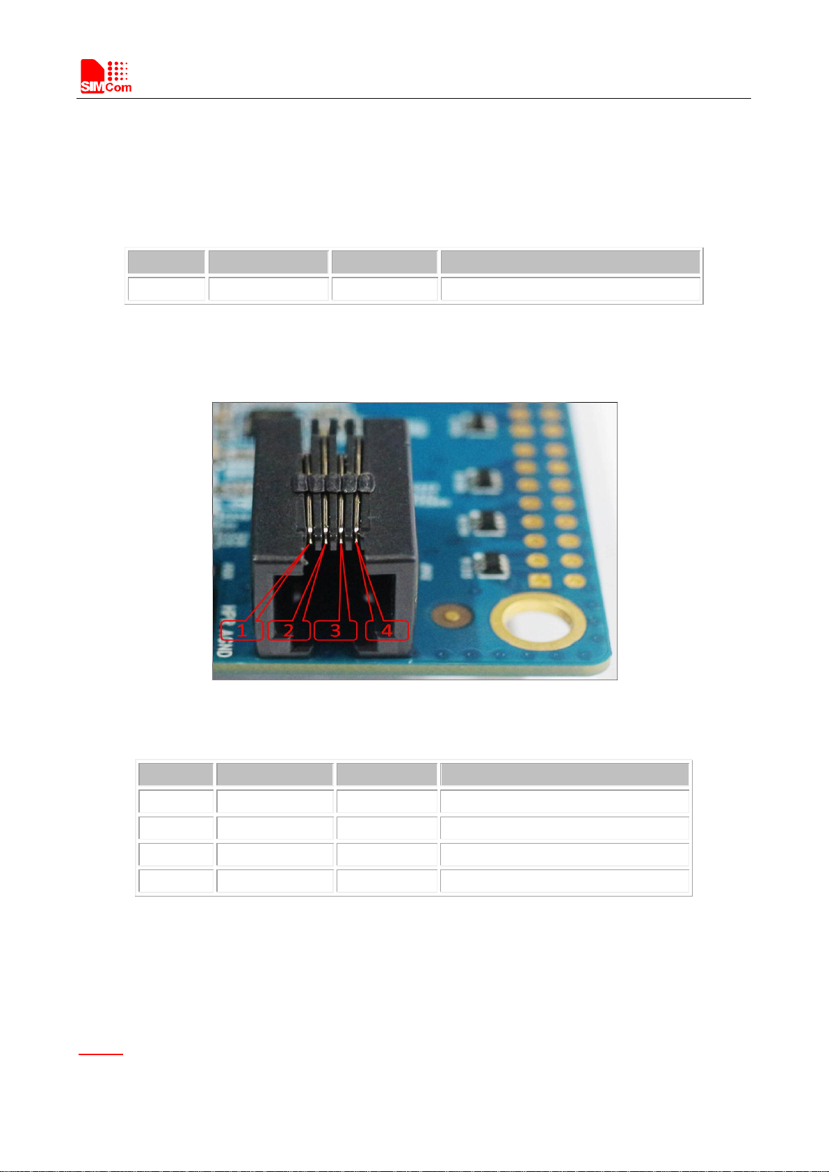
3.2Audio Interface
Figure4: Audio Interface
Headset interface:
Pin
Signal
I/O
Description
1
MICN
I
Negative microphone input
2
SPKN
O
Negative receiver output
3
SPKP
I
Positive receiver output
4
MICP
O
Positive microphone input
3.3 SIM card interface
Main SIMCard holder (J202) is the primary SIM interface, Secondary slot (J203) is for special module which
supports dual sim.
Notice:
Here for SIM7500, just use main SIMcard holder (J202).

Smart Machine Smart Decision
SIM7500_EVB Kit_User Guide_V1.01 10 2017-12-12
3.4 USB Interface
EVB USB interface (A) actually is USB-to-UART port which could be imaged to two virtual ports.
Figure 5: Virtual serial port
Enhanced COM port: AT communication
Standard COM port: Debug (used for 2G module only)
Notice
CP2105 driver is available here:
http://www.silabs.com/products/mcu/Pages/SoftwareDownloads.aspx
3.5 Power switch
After 5V Adapter is inserted ,switch S201 on, then power LED (D201) will be solid on.
3.6 POWER_ON Button
After giving power to EVB,press the POWER_ON button for more than 1.5 seconds, the module will be
turned on, the network LED light (D401) will blink.
3.7 RF switch
Figure 6: RF switch
Autres manuels pour SIM7500 Series
3
Table des matières
Autres manuels SimCom Matériel réseau


Manuels Matériel réseau populaires d'autres marques

Matrix Switch Corporation
Matrix Switch Corporation MSC-HD161DEL Manuel utilisateur

B&B Electronics
B&B Electronics ZXT9-IO-222R2 Manuel utilisateur

Yudor
Yudor YDS-16 Manuel utilisateur

D-Link
D-Link ShareCenter DNS-320L Manuel utilisateur

Samsung
Samsung ES1642dc Instructions d'utilisation

Honeywell Home
Honeywell Home LTEM-PV Instructions de montage


