AP10S Date: 04.09.2017 Art. No. 87826 Mod. status 269/17 Page 3 of 48
6.3.2 Node address......................................................................................................19
6.3.3 Parameter address...............................................................................................19
6.3.4 Control word ......................................................................................................20
6.3.5 Status word........................................................................................................20
6.3.6 Data..................................................................................................................21
6.3.7 Check sum..........................................................................................................21
6.4 Synchronization .....................................................................................................22
6.5 Error telegram........................................................................................................22
6.5.1 SIKONETZ5 error codes.........................................................................................22
6.6 Communication errors .............................................................................................23
6.7 Communication monitoring ......................................................................................23
6.7.1 Bus-Timeout.......................................................................................................23
6.7.2 Programming interlock.........................................................................................23
6.8 Auto-ID.................................................................................................................24
6.9 Parameter description .............................................................................................26
6.9.1 00h: Node address...............................................................................................26
6.9.2 01h: Baud rate ...................................................................................................26
6.9.3 02h: Bus Timeout................................................................................................26
6.9.4 03h: Response parameter to a set point write access................................................27
6.9.5 04h: Keys enable time: Configuration start delay .....................................................27
6.9.6 05h: Key function enable1: Calibration enable.........................................................27
6.9.7 06h: LED flashing................................................................................................28
6.9.8 07h: LED3 (green right) .......................................................................................28
6.9.9 08h: LED2 (red left) ............................................................................................28
6.9.10 09h: LED1 (green left) .........................................................................................29
6.9.11 0Ah: Decimal places ............................................................................................29
6.9.12 0Bh: Display divisor (ADI) ....................................................................................29
6.9.13 0Ch: Direction indicators (CW, CCW).......................................................................30
6.9.14 0Dh: Display orientation ......................................................................................30
6.9.15 0Eh: Configuration programming mode...................................................................30
6.9.16 1Bh: Counting direction.......................................................................................31
6.9.17 1Ch: Resolution or measurement steps per revolution...............................................31
6.9.18 1Eh: Offset value ................................................................................................32
6.9.19 1Fh: Calibration value..........................................................................................32
6.9.20 20h: Target window1 (near field) ..........................................................................33
6.9.21 21h: Positioning type (loop type)..........................................................................33
6.9.22 22h: Loop length ................................................................................................33
6.9.23 28h: Operating mode...........................................................................................34
6.9.24 30h: Display in the 2nd row ...................................................................................34
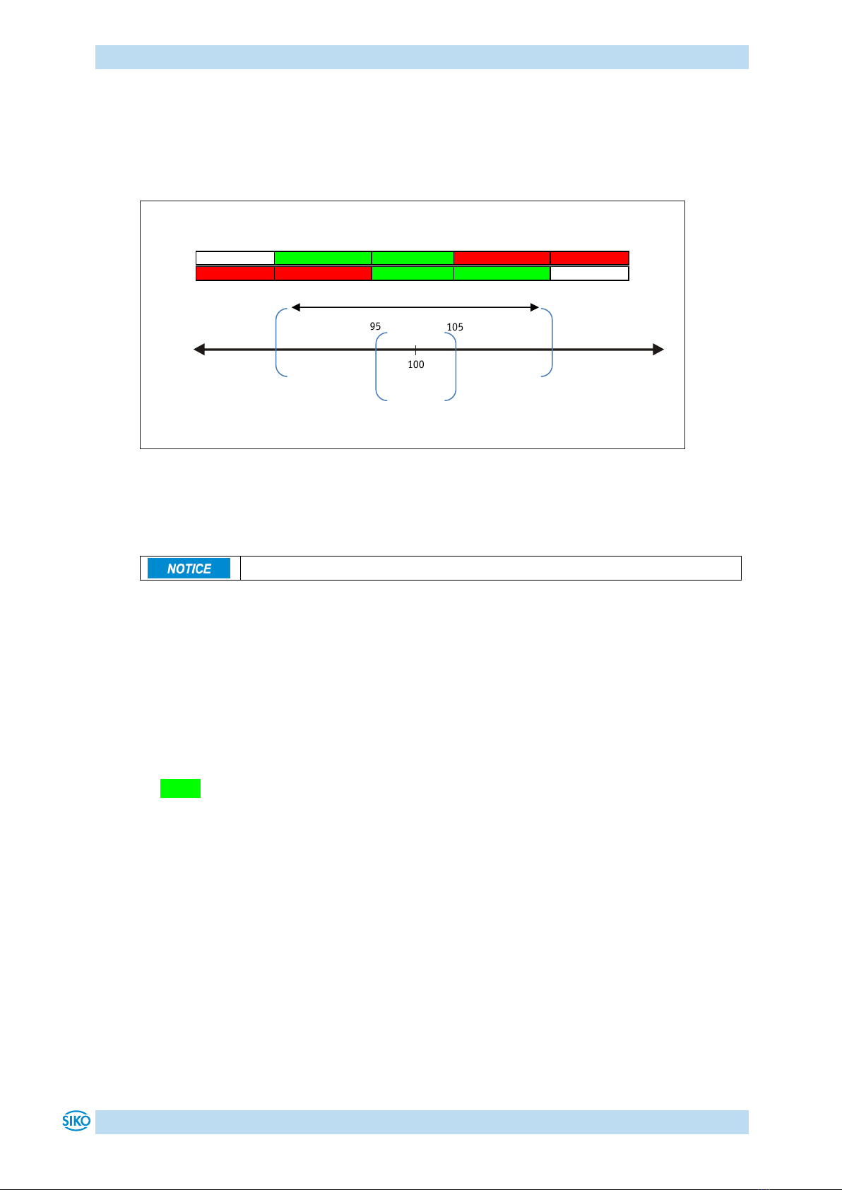
6.9.25 31h: Target window2 (extended)...........................................................................35
6.9.26 32h: Target window2 visualization.........................................................................35
6.9.27 33h: Application of the display divisor (ADI application)..........................................35
6.9.28 34h: Formation of the differential value .................................................................36
6.9.29 35h: Key function enable2: Incremental measurement enable....................................36