Sigma Controls 700 Series Manuel utilisateur

1
VISIT OUR WEBSITE SIGMACONTROLS.COM
700 SERIES ‘MM’
MOTOR MONITOR
INSTRUCTION MANUAL
700 MM MANUAL 042414

2
TABLE OF CONTENTS
INTRODUCTION………………………………………… 3
Ordering Information
Specifications
Features
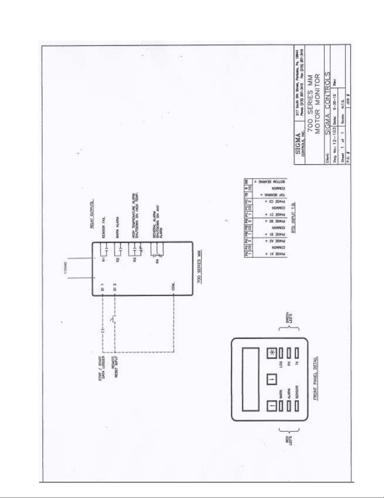
WIRING…………………………………………………… 6
D g # 12-103 (700 MM Motor Monitor)
Sho ing: Inputs (8) 100 OHM RTD
Digital Output (4) Form ‘C’ Relays
PROGRAMMING AND INITIAL SETUP……………... 7
Input Range Selection
Terminal Block Detail
Initial Setup & Programming
Overvie /Key Description
DIAGNOSTICS……………………………………………
11
PROGRAMMING RECORD SHEET…………………...
12
TROUBLESHOOTING MAINTENANCE.…………..
13
WARRANTY……………………………………………… 14
*U.L. APPLIES TO OPTIONAL ENCLOSURE

3
INTRODUCTION:
The Sigma 700 Series ‘MM’ Motor Monitors are state of the art microprocessor based, user configurable
instruments for the monitoring and alarming of embedded temperature probes in electric motor indings
and bearings.
The 700 Series float controllers perform the follo ing functions.
Displays information in alpha and numeric format
Allo s full user selection of all system variables
Monitors critical alarms ( inding/bearings overtemperature, etc.)
Provides relay outputs for motor high temp arning and motor shutdo n
Visual alarms (LED)
Available Nema 4X enclosures
ORDERING INFORMATION:
Wall Mount Nema 4X Enclosure Sigma 700 Series MM
SPECIFICATIONS:
DIGITAL INPUTS (8 ea.)
Digital 10-30V DC (Grounding) (Optional)
100 OHM RTD Temperature Probes (8 ea.)
RELAY OUTPUTS: (4 ea.)
SPDT, Form ‘C’ 5A Relay
DISPLAY:
LCD, 2 line Alphanumeric, Backlit.
LOOP POWER:
24VDC regulated output, 100MA max. ( ith 110VAC option).
3 USER KEYS:
Up, Do n, Enter
ACCURACY:
0.1% of calibrated span
LOCKOUT:
User pass ord, user configurable
INPUT IMPEDANCE:
Voltage 100K, current 100 OHMS

4
POWER:
24VDC, (110VAC optional)
ENVIRONMENTAL:
Operating, 0-65° C
Storage, -40° -80° C
R.H., 0-90% non condensing
ENCLOSURE:
¼ DIN, ABS plastic 96 X 96 X 110MM or Nema 4X all mount
FRONT PANEL:
Gasketed Nema 4X Hinged Windo
TERMINAL STRIP:
(24) Removable for ease of iring 28 – 16 AWG
CONNECTIONS:
Removable scre terminal blocks 28 – 16 AWG ire. (27 ith 110VAC option)
CONTROL OUTPUTS:
4 relay outputs, user programmable, SPDT Form ‘C’ relays 5 AMP.
CPU Activity Monitor
PROGRAMMING:
Menu based, all parameters and setpoints are user configurable via menu prompts and user keys.
The preconfigured screens and ‘pull do n’ sub menus ith English prompts assures rapid setup
and commissioning.
1 YEAR WARRANTY
OPTIONS:
4 M/Byte data logging ith USB Port
MODBUS® Master/Slave
Net ork allo s multiple units to be connected together for distributed applications or remote
monitoring SCADA applications.
EXPANSION CARDS:
Significant expansion is possible via additional control boards and ‘MODBUS®’ net orking.

5
FEATURES:
Microprocessor Based
LCD Display
3 Function Keys
Isolated 24VDC Sensor Po er ( ith 110VAC option)
4 Form ‘C’ Relay Outputs
Fully User Programmable in English
1 Ea. RS485 Port (Programming and SCADA) MODBUS® Master/Slave.
CPU Activity Monitor
WIRING DETAIL
See D g # 12-103
CAUTION
!
All electrical wiring must be in accordance with all local state and national
codes that apply.
Do not exceed the rated current of the D.C. power supply (100MA) or the form
’C’ relay outputs (5A/240VAC resistive).
WARNING
Hazardous voltages are present within the enclosure. Installation or service
should only be carried out by trained personnel.
6
7
PROGRAMMING SETUP
Review Screens
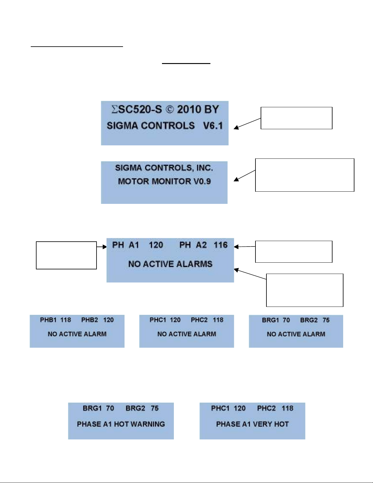
The 700 Series MM utilizes ‘plain English’ menu driven screens hich are sequential and intuitive.
When the unit po ers up, the startup screen ill appear as follo s:
After the initial screens have appeared, the unit ill sho the ‘MAIN SCREEN’ hich scrolls as
sho n belo .
NOTE: Should any channel go into “WARN’ or ALARM modes, screen will continue to
scroll with the alarm message on the bottom line and the WARN and/or HIGH temperature RED
LED(s) will be lit.
Soft are Version #
Identifies the unit
Function and Version #
Indicates Phase
‘A’ #1 Temp.
Indicates Phase ‘A’
#2 Temp.
This message i
ndicates
that no Alarms are
active
8
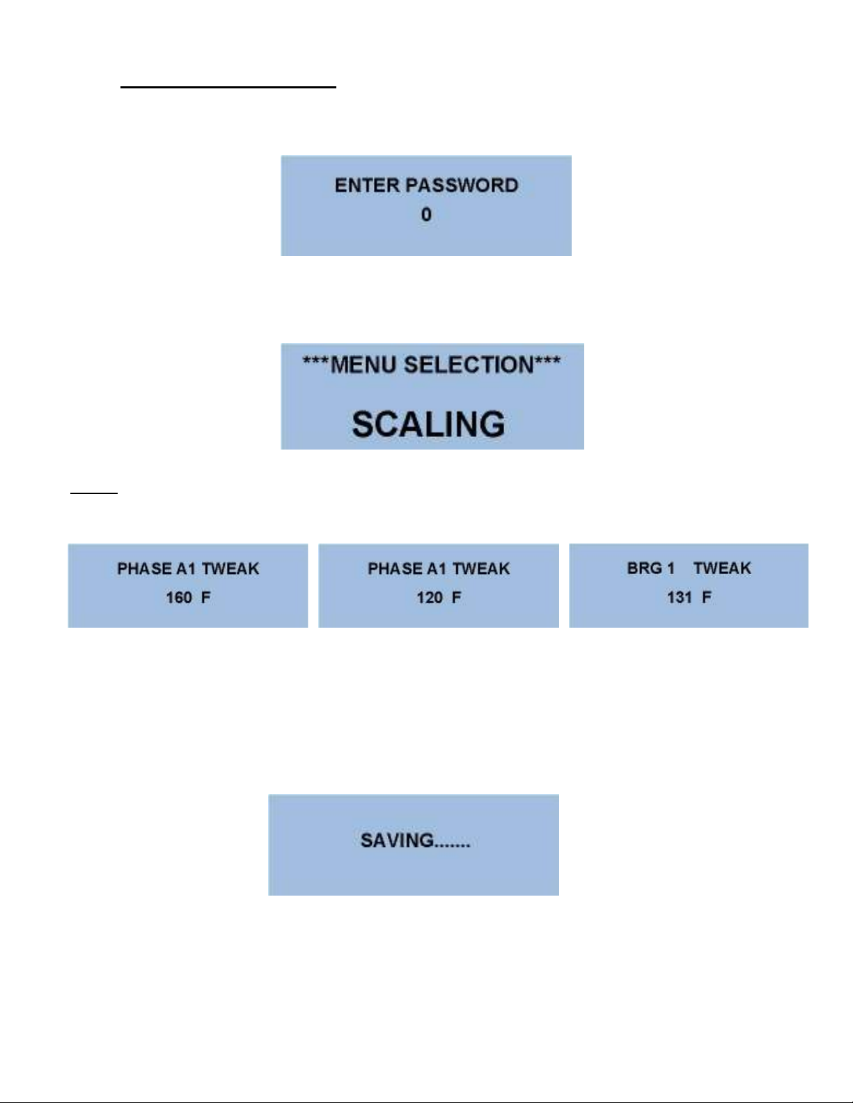
PROGRAMMING SCREENS
From the Main Menu, Press the button to access the Pass ord Screen:
.
Use the buttons to enter the preprogrammed pass ord, then press to advance to the Menu
Screens.
Use the buttons to advance to the ‘Scaling’ screen.
NOTE: Since the unit is designed for a fixed range sensor scaling is automatic. Ho ever due to
inconsistencies in some sensors a ‘TWEAK’ screen is provided to make minor adjustments.
Use a RTD simulator to inject a kno n temperature value into each channel and use the buttons to
make the screen value match the injected signal.
Press the button to advance through all input screens and hen complete the controller ill save all
changed values.
And return to the Main Screen.
9
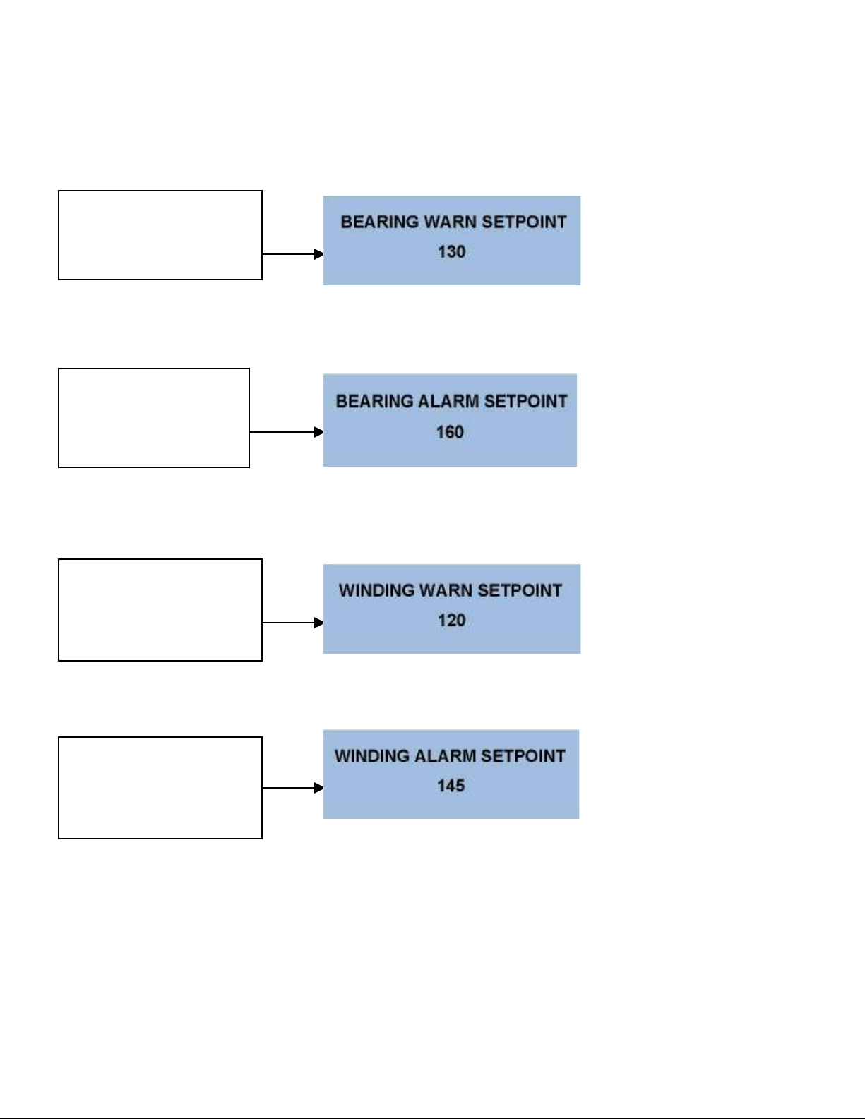
This completes the ‘Scaling’ section. Press to save any changed values and return to the ‘Main Menu’
Screen. As previously described, enter the MENU selection and select the ‘SETPOINTS’ menu, here
process setpoints are entered. The first screen is the bearing arning setpoint.
Use to change or press to advance to the: Bearing Setpoint Screens.
Use to change or press to advance to the: Winding Setpoint Screens.
Use to change or press to advance to the:
Press the to save values and return to the ‘Main Screen’.
This is the temperature hich
brings up the ‘HOT’ alarm and
turns on the ‘Warn’ LED and
relay output.
This is the temperature hich
brings up the ‘VERY HOT’
alarm and turns on the
‘Alarm” LED and relay
output.
This is the temperature hich
brings up the phase ’HOT’
alarm and the turns on the
Alarm LED and the relay
output.
This is the temperature hich
brings up the phase ‘VERY
HOT’ alarm and turns on the
Alarm LED and the relay
output
.
10
ADVANCE TO THE ‘SETUP’ MENU’
Setup screen provides ‘global’ parameters hich affect overall performance and operation.
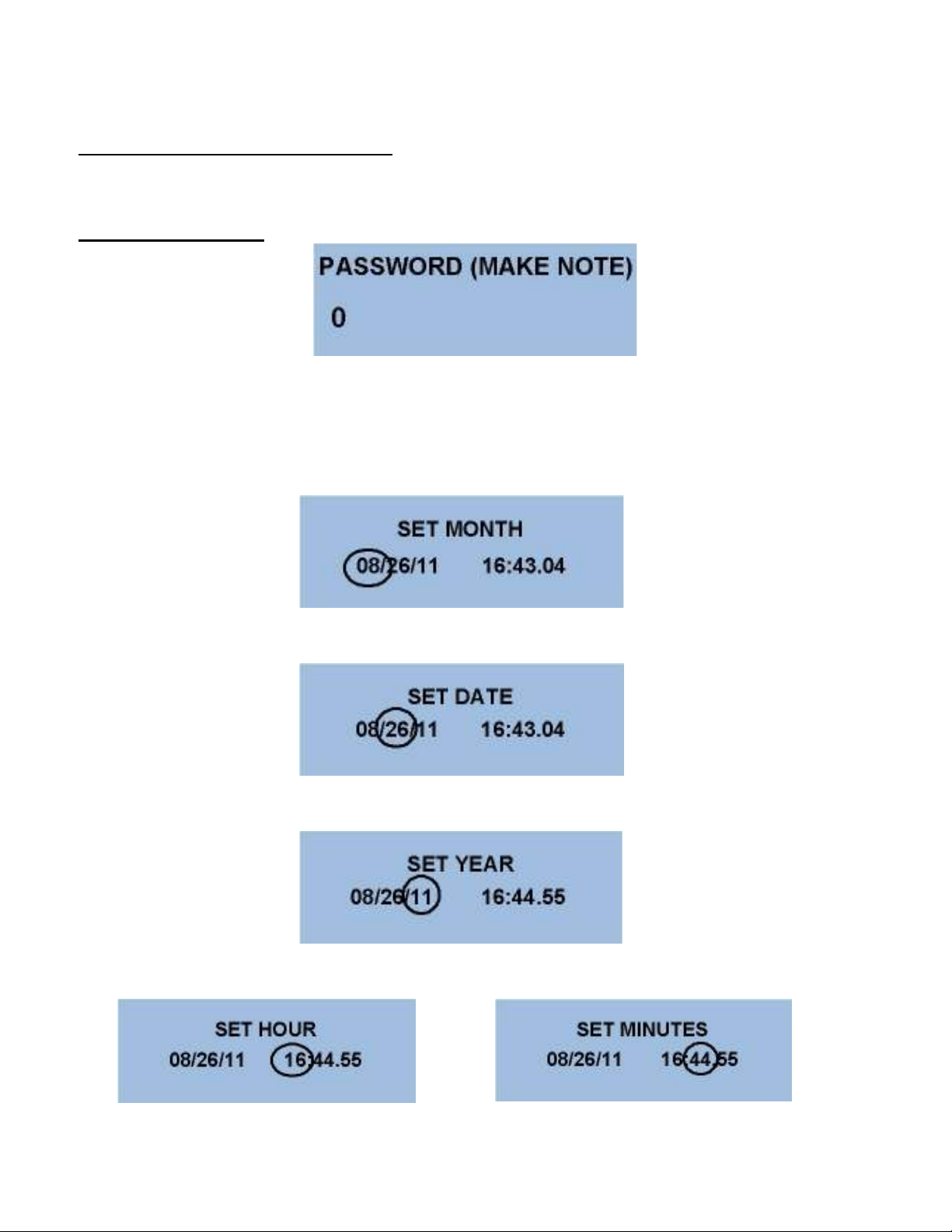
PASSWORD SCREEN
Setting a pass ord ‘Locks’ out unauthorized access to program items. NOTE: Please make a note of
the password value if changed. Access to the Menus will be unavailable without the correct
password.
Press to advance to the clock/calendar settings.
Use the buttons to change the month. Press to advance.
Use the buttons to change the year. Press to advance.
Use the buttons to change the other settings as previously described.
Autres manuels pour 700 Series
1
Ce manuel convient aux modèles suivants
1
Table des matières
Autres manuels Sigma Controls Instrument de mesure

Manuels Instrument de mesure populaires d'autres marques


Endress+Hauser
Endress+Hauser Proline Promag 50 Caractéristiques techniques

Siemens
Siemens SITRANS F Coriolis FCT030 Manuel de la liste des pièces

KLINGER
KLINGER CMF V Series Manuel utilisateur

EXFO
EXFO FTB-2 Manuel d'exploitation et d'entretien

Keysight
Keysight M8290A Manuel utilisateur

ADTEK
ADTEK MW-5 Manuel utilisateur