Sigicom INFRA C22 Manuel utilisateur
Manual
Copyright © Sigicom AB 2020 Art.no. ML089-05222-0En
INFRA C22
Wireless Vibration Monitor
Art no. 080-05222-0
Manual ver. K
Valid for firmware 2.3.0

Copyright © Sigicom AB 2020
2
IMPORTANT SAFETY INSTRUCTIONS
–read this before use
Operating conditions and limitations:
•The C22 shall not be submerged.
•Safe operating temperature range is -30 to +50 ºC
(-22 to +122 ºF).
•This instrument includes built-in radio transmitters and
antennas. It should be installed away from the operator or third-
party persons to be safe; a recommended minimum distance is
1 m (3 ft.).
•Before installing the instrument, make sure there are no
restrictions of the use of radio transmitters at the intended site.
•Do not use the instrument in presence of flammable fumes or
gases, or in explosive atmospheres.
Li-Ion batteries:
•Only use batteries and power supplies provided or recommended by
Sigicom, see chapter 8Accessories.
•Do not use C22 batteries in other products than applicable Sigicom
products.
•A power source connected to the C22 must not be able to supply more
than 20V and 3A. A solar panel with maximum 25W power and with an
open-circuit voltage of 22V is allowed.
•Replacement and other handling of the batteries shall only be executed
by persons who have carefully read the instructions in this manual.
•Never keep the batteries at temperatures above 50ºC (122ºF).
•Transportation of Li-Ion batteries by aircraft is regulated by UN and
IATA. See Appendix B - Appendix D.
•Transportation by road or railway is exempt from dangerous goods
transportation regulations. Care should still be taken with handling and
packaging to avoid severe injury.
•If damaged, the batteries should be individually embedded into sand in a
sturdy plastic drum container during transport. It is also recommended
to affix a “Lithium Ion” label with an additional text: ‘Damaged
batteries’ on the package.
A worn-out battery, a battery with cracks or with signs of swelling or
leakage, shall be replaced immediately.
Note! Damaged or worn out batteries are prohibited in air freight.

Copyright © Sigicom AB 2020
3
•Never incinerate, disassemble or expose the batteries in water.
•If the terminals of the battery are shorted, the battery may become very
hot and permanently damaged.
•Prepare your warehouse and charging sites according to Appendix C
and Appendix D.
•Use stand-alone chargers in a well-ventilated room, well away from
flammable material, open fire and electric sparks.
•If the battery case is penetrated, it may burn with open flame.
This equipment falls under the Waste Electrical and Electronic Equipment
Directive (WEEE directive) 2012/19/EU, category 9: monitoring and
control instruments:
•Scrapped equipment should be sent back to the manufacturer of
the equipment (Sigicom AB) for proper handling according to
the WEEE directive.
•Sigicom uses a certified local partner for recycling of scrapped
equipment.
The batteries used in this equipment falls under the Battery Directive
2006/66/EC:
•When the equipment is sold to customers in the European Union
(EU), except Sweden, the customer is the importer of the battery.
The customer must follow the rules and regulations as ratified by
each individual European Union member state or send the
battery/equipment back to the manufacturer of the equipment
(Sigicom AB) for proper disposal.
•Swedish customers can recycle the battery in the national battery
collection system.
•Users outside the EU may send the batteries back to the
manufacturer of the equipment (Sigicom AB) for proper
disposal.

Copyright © Sigicom AB 2020
4
Table of Contents
1. Introduction ....................................................................................... 7
1.1. INFRA System......................................................................... 7
1.2. INFRA C22 Vibration Monitor................................................ 7
1.3. INFRA C22 Enclosure............................................................. 8
1.4. Unpacking and Parts Identification.......................................... 9
2. Product Description......................................................................... 10
2.1. Keypad................................................................................... 10
2.2. Display................................................................................... 11
2.3. Batteries ................................................................................. 12
2.4. External Power Connector ..................................................... 12
2.5. USB Connector (Mini-B Type).............................................. 12
2.6. Memory Card......................................................................... 13
2.7. SIM Cards.............................................................................. 13
3. Measuring Parts............................................................................... 15
3.1. Measuring Hardware.............................................................. 15
3.1.1. Vibration Sensor................................................................ 15
3.1.2. Analog Electronics ............................................................ 15
3.1.3. Analog-Digital Conversion................................................ 15
3.1.4. Digital Signal Processing................................................... 15
3.2. Measuring Logic.................................................................... 16
3.2.1. Measurement Standards..................................................... 16
3.2.2. Interval Measurements....................................................... 16
3.2.3. Transient Recording .......................................................... 18
3.2.4. Overload Handling ............................................................ 18
3.3. Data Storage........................................................................... 19
3.3.1. Transient Data.................................................................... 19
3.4. Additional Hardware.............................................................. 19
3.4.1. Humidity Sensor................................................................ 19
3.4.2. GPS Receiver..................................................................... 19
4. Configuration and Installation......................................................... 20
4.1. Configurations and Settings................................................... 20
4.1.1. INFRA Net Communication Schedule .............................. 20
4.1.2. Flight Mode ....................................................................... 20
4.1.3. Configuration Menu .......................................................... 20
4.1.4. INFRA Net Messages........................................................ 20
4.1.5. Factory Default Settings.................................................... 21
4.2. Mounting................................................................................ 21

Copyright © Sigicom AB 2020
5
4.2.1. Wall Mounting................................................................... 21
4.3. Site Startup Check.................................................................. 22
5. Operation......................................................................................... 23
5.1. Startup.................................................................................... 23
5.2. Start Monitoring..................................................................... 23
5.2.1. Sensor Test ........................................................................ 24
5.3. Stop Monitoring..................................................................... 24
5.4. INFRA Net Communication .................................................. 25
5.4.1. Automatic INFRA Net Communication............................ 25
5.4.2. Manual INFRA Net Communication................................. 25
5.4.3. More Communication Information.................................... 26
5.5. Power Off............................................................................... 26
5.6. Power Lost ............................................................................. 26
5.7. GUI Menu.............................................................................. 28
5.7.1. Monitoring config.............................................................. 28
5.7.2. Communication Mode ....................................................... 29
5.7.3. Clock Set ........................................................................... 30
5.7.4. Clock Format..................................................................... 30
5.7.5. USB Memory Interface Mode ........................................... 31
5.7.6. Firmware Upgrade............................................................. 32
5.7.7. Errors and Warnings.......................................................... 34
5.7.8. Power off and Reboot........................................................ 35
5.8. GUI Passcode......................................................................... 36
5.9. INFRA Net Remote Control .................................................. 37
5.9.1. Remote Firmware Upgrade................................................ 38
5.9.2. Remote Reboot .................................................................. 38
5.9.3. Remote Shut Down............................................................ 39
5.9.4. Remote Update GPS Position............................................ 39
5.10. Removal and replacement of Li-Ion batteries:....................... 27
6. Other Functions ............................................................................... 40
6.1. Disable Communication......................................................... 40
6.2. GPS position .......................................................................... 40
6.3. GPS time synchronization...................................................... 41
6.4. Time Synchronization through Internet ................................. 41
6.5. Daylight Saving Time............................................................ 41
7. Technical Specifications.................................................................. 43
8. Accessories...................................................................................... 44
9. Maintenance and Calibration........................................................... 45

Copyright © Sigicom AB 2020
6
10. Contact and Support........................................................................ 46
Appendix A. Battery Level Limits ......................................................... 47
Appendix B. Li-Ion Battery Transport................................................... 48
Appendix C. Safe Handling of Li-Ion Batteries..................................... 49
Appendix D. In Case of Li-Ion Battery Fire........................................... 50
Appendix E. Errors and Warnings ......................................................... 51
Appendix F. Measurement Standards.................................................... 53
Appendix G. Standards with Frequency Weighting............................... 67
Appendix H. British Standard BS 6841 (VDV) ..................................... 70
Appendix I. Set another APN (external SIM)....................................... 72
Developed and manufactured by:
Sigicom AB
Glasfibergatan 8
SE –124 45 Älvsjö, Sweden
Support: support@sigicom.com

Copyright © Sigicom AB 2020
7
1. Introduction
1.1. INFRA System
The INFRA field measurement system consists of rugged sensors which
sends data and status to INFRA Net, where it is processed, stored and
presented through a web interface. There are sensors which monitor
several important quantities at construction sites and infrastructure
projects, such as vibration, noise and dust etcetera.
All data is sent to INFRA Net, using the built-in cellular modem, at
various occasions:
•Monitoring is started or stopped.
•A trigger event has occurred.
•An error event has occurred, e.g. low battery.
•Manual communication is performed by the operator.
•At scheduled communication.
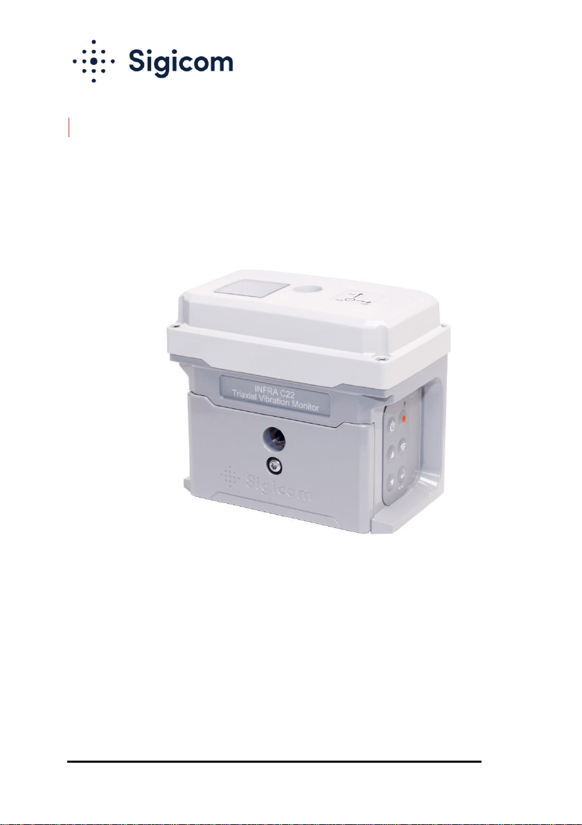
1.2. INFRA C22 Vibration Monitor
The C22 instrument is a complete triaxial wireless vibration monitor
measuring in three directions, vertical, longitudinal, and traverse. It
consists of vibration sensor elements, analog measuring electronics,
analog-digital converters, an embedded microcontroller/DSP for digital
signal processing etc., a small color display, a six-button keypad, a
memory card, a cellular modem, antennas and batteries.
The C22 instrument requires INFRA Net for full remote control
capability, data presentation, alarms/alerts configuration and setup, and
instrumentation settings. However, the majority of instrument settings can
be changed directly at the unit using the keypad/display.

Copyright © Sigicom AB 2020
8
1.3. INFRA C22 Enclosure
The enclosure base is milled out of solid aluminum and includes:
•A horizontal hole for wall-mounting (M6 or ¼” bolt).
•A vertical hole for floor-mounting (M6 or ¼” bolt).
•A front lid covering the two batteries.
•A plug at the back of the enclosure covers a desiccant bag which
needs to be replaced at regular intervals (see chapter 9).
•A plastic cap on the top covers the antennas. Removing this cap
gives access to the microSD memory card and SIM card, but
will seldom need to be opened.
•A separate hole at the lower left side of the unit may be used for
a wire to lock the unit to a fix and solid structure for theft
prevention.
•Three mounting setoff screws, located on the back of the
instrument enable sufficient, secure and plumb contact between
instrument and uneven vertical (or near vertical) surfaces. These
screws are not used for mounting (attachment) but used to
ensure that the instrument is plumb in the vertical direction
when attached (mounted) to a vertical surface.
•All lids, plugs and connectors are O-ring sealed.
Note! C22 instruments are not intended to be submerged in water.

Copyright © Sigicom AB 2020
9
1.4. Unpacking and Parts Identification
The INFRA C22 Vibration Monitor has been shipped in protective
packaging. Please keep this and use it when transporting your equipment.
Verify the package content with the following list:
•C22 Vibration Monitor instrument.
•Foam (shock protection during transportation).
•Two (2) batteries, either inserted in unit or separate.
Note! Because of shipping regulations, batteries are charged
below 30% state of charge at delivery.
•Calibration document.
Any damage or omission should be reported immediately to Sigicom.
Keep record of the instrument’s serial number. You will be asked to give
this number in any C22 related communication you may have with
Sigicom.
Copyright © Sigicom AB 2020
10
2. Product Description
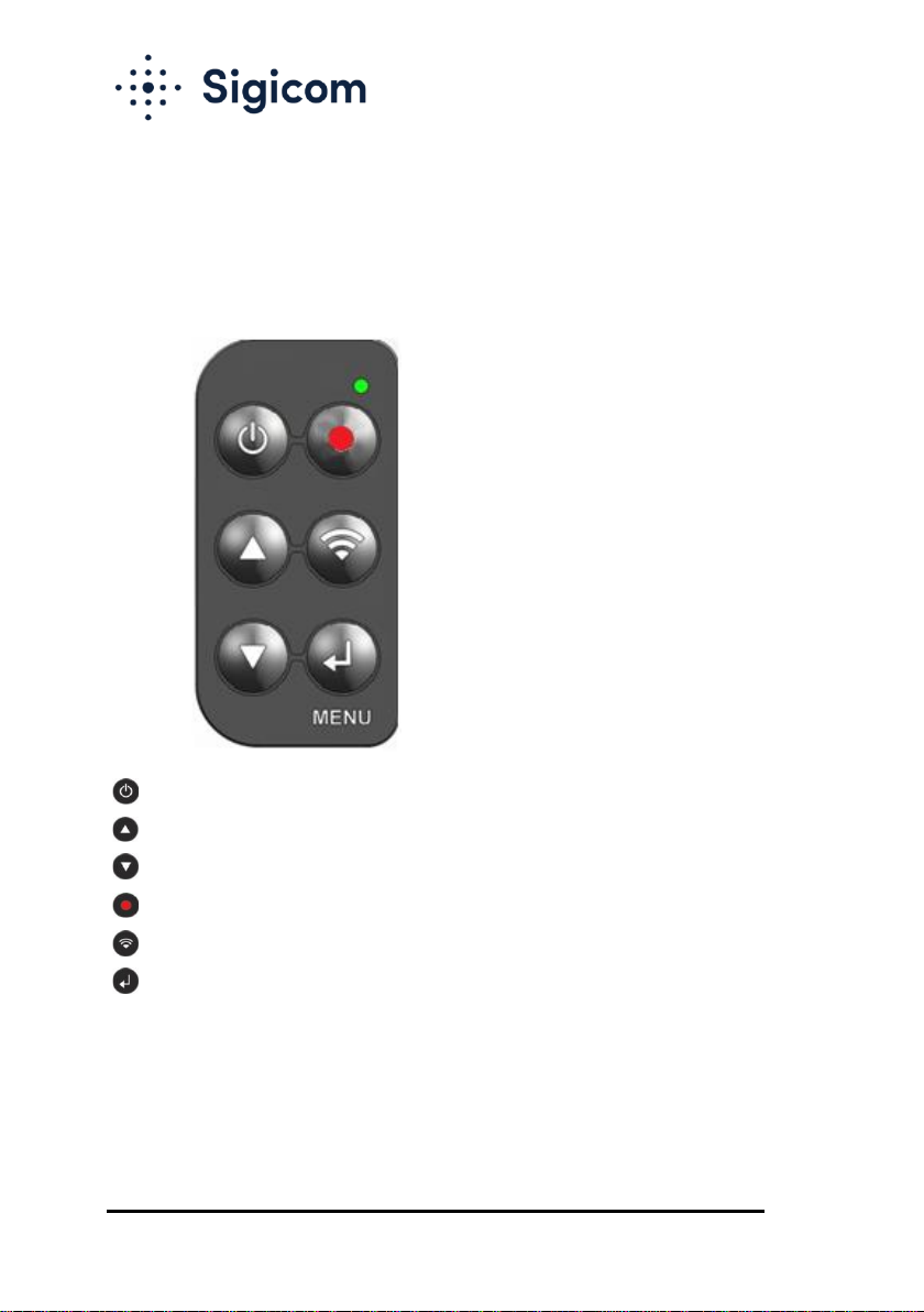
2.1. Keypad
A six-button keypad is placed on the right-hand side of the unit.
Display ON / Exit / Cancel / Display OFF
Up / Increase
Down / Decrease
Monitoring start/stop
Communication status
Menu / Enter / Acknowledge / Activate
For more information about operation of the graphical user interface, see
chapter 5 Operation.
Note! The LED indicator (the green circle in the picture above) is
only used at firmware upgrade.
Autres manuels pour INFRA C22
2
Ce manuel convient aux modèles suivants
1
Table des matières
Autres manuels Sigicom Moniteur


