Siegenia-AUBI KFV Genius Manuel utilisateur

Window hardware
Assembly instructions
Automated latch release
Automatic door lock
Sliding door hardware
Ventilation and building technology
Door hardware


1Last update: 01.08.2013
Assembly instructions Automated latch release
ENGLISH
Contents
Target group of this documentation............................................................... 2
Intended use................................................................................................. 2
Improper use................................................................................................ 2
Safety notes.................................................................................................. 2
Explanation of symbols................................................................................. 2
Installation.................................................................................................... 3
Connections................................................................................................... 4
Cable links.................................................................................................... 6
Fitting an internal release push-button (optional)........................................... 7
Fitting the infra-red eye (optional)................................................................. 7
Wiring diagram for type A automated latch release...................................... 8
Wiring diagram for type F automated latch release....................................... 9
Technical specifications.................................................................................. 10
Liability......................................................................................................... 10

2Last update: 01.08.2013
Automated latch release Assembly instructions
Target group of this documentation
This documentation is intended to be used by specialists only. All work described in this document is to be performed
by experienced professionals with training and practice in the assembly, installation and maintenance of the automa-
ted latch release and its individual components. Safe and proper assembly of this automated door lock is not possible
without expert knowledge.
Intended use
UÊ The automated latch release is used in combination with automatic locking systems to unlock doors electrically.
UÊ It is suitable for installation in timber, aluminium, steel and PVC front doors for residential and public buildings.
UÊ All assembly and electrical installation work must be carried out according to our assembly and installation instruc-
tions. Wiring the unit incorrectly can irreparably damage its electronic components.
UÊ The automated latch release can be connected to an external access control system (e.g. wireless, transponder or
fingerprint scanner system) via a voltage-free contact (switching time: min. 1 second).
UÊ Use the automated latch release only when it is in a technically sound condition. Do not modify the unit's components
in any way.
UÊ Use the automated latch release only with genuine KFV accessories.
Improper use
UÊ The automated latch release must not be installed in moisture-prone areas or areas with a corrosive atmosphere (e.g.
electroplating shops).
UÊ The length of the cable between the power supply and the automated latch release must not exceed 13 m.
Safety notes
UÊ Work on an 230 V AC mains power supply may only be performed by a qualified electrician.
UÊ All work on the 230 V AC mains power supply must be carried out in compliance with the current German VDE regu-
lations (e.g. VDE 0100) and any relevant country-specific requirements.
UÊ All-pole safety isolation should be used when fitting the power lead on-site.
UÊ Some external access control systems available on the market transmit a brief "open" signal when the operating
voltage is switched on. This can mean that the automated latch release will open the door following a power cut. If in
doubt, please contact the system manufacturer.
Explanation of symbols
Ø16
50
180
Milling cutter or drill diameter Groove depth from profile
Groove length
Where power supply cables are routed parallel to data cables (IDSN, DSL etc), interference can occur, eg: with
the data transfer speed.
Warning
3Last update: 01.08.2013
Assembly instructions Automated latch release
ENGLISH
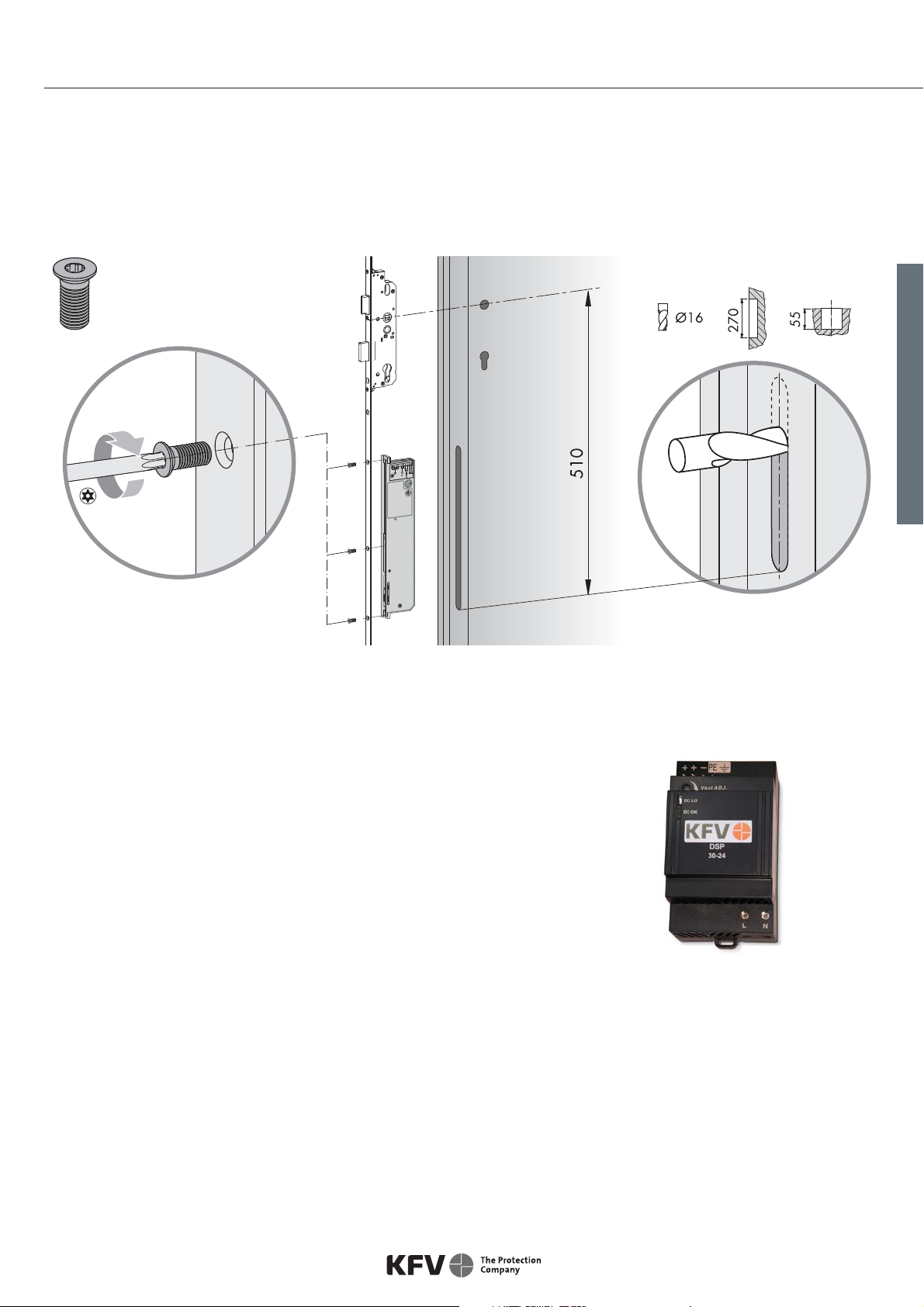
Installation
Automated latch release
The automated latch release is supplied unassembled. Before it can be used it must be screwed onto the auto-
matic locking system.
3x
Fig. 1: Fitting the automated latch release
Fitting the power supply
UÊ The power supply ensures that the automated latch release is supplied with
the right voltage.
UÊ Its casing is designed to be fitted on a standard DIN EN 60715 mounting
rail.
UÊ One power supply can supply a maximum of 2 automated latch releases,
each connected to one KFV access control (wireless, transponder, infra-red
or fingerprint scanner) system.
UÊ The power supply comes with a permanent connection. A easily-accessible
means of disconnecting it must be integrated into the power supply circuit. Fig. 2: Power supply
Fitting cables
Various types of cable are available for connecting the power supply to the automated latch release.
Each cable is marked with a band to show where it must be plugged into the automated latch release.
Important:
UÊ When routing cables behind the secondary sash, ensure that they are not vulnerable to damage from the drive rod or
other moving parts.
UÊ The shield must be connected to earth on the power supply side. On the automated latch release side, connection of
the shield is not necessary.

4Last update: 01.08.2013
Automated latch release Assembly instructions
Connections
Connec-
tions
Type
A
Type
BFunction
A, B, C, D
B, C, D, 2
Connection for the infra-red eye, which
sends infra-red signals to the GENIUS
door lock
Connection for the KFV fingerprint
scanner
2, 3
24 V DC operating voltage
Terminal 2 = + (positive)
Terminal 3 = -- (negative)
4
External unlocking signal.
In both operating modes, if +24 V DC
is applied to this terminal for t1 s, the
door will be opened
Fig. 3: Automated latch release connections
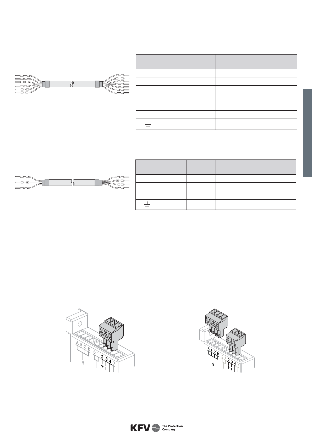
Cable types
Type F
Always used together with type B.
0
1
2
3
4
7
Cable
no.
Band
colour
Cable
colour Function
0 Black Grey -
1 Brown Yellow -
2 Red White Operating voltage (+) 24 V DC
3 Blue Brown Operating voltage (--) negative
4 Yellow Green External "unlock" signal
7 Violet Pink -
Fig. 4: Cable type F (for connection of automated
latch release)
Type B
Always used together with type F.
0
1
4
7
+
-
Cable
no.
Band
colour
Cable
colour Function
0 Black Grey -
1 Brown Yellow -
4 Yellow Green External "unlock" signal
7 Violet Pink -
-- Blue Brown Operating voltage (--) negative
+ Red White Operating voltage (+) 24 V DC
White Blue Shield
Fig. 5: Cable type B (for connection of power
supply)
5Last update: 01.08.2013
Assembly instructions Automated latch release
ENGLISH
Type K
Cable
no.
Band
colour
Cable
colour Function
4 Yellow Green External "unlock" signal
-- Blue Brown Operating voltage (--) negative
+ Red White Operating voltage (+) 24 V DC
White Blue Shield
Fig. 6: Cable type K
(connects automated latch release to
power supply)
Type E
Fig. 7: Cable type E (connects automated latch
release to power supply) -type A only-
0
1
2
3
4
7
0
1
4
7
+
-
4
+
4
+
Cable plugs for the automated latch release
UÊ To facilitate installation of the automated latch release, the plug can be removed by pulling it upwards.
UÊ There are letters on the plug to indicate where the various cables should be plugged in.
234
234
ABCD
Type A automated latch release Type F automated latch release
Fig 8: Cable plugs for the automated latch release
Cable
no.
Band
colour
Cable
colour Function
0 Black Grey -
1 Brown Yellow -
4 Yellow Green External "unlock" signal
7 Violet Pink -
-- /3 Blue Brown Operating voltage (--) negative
+/2 Red White Operating voltage (+) 24 V DC
White Blue Shield

6Last update: 01.08.2013
Automated latch release Assembly instructions
Cable links
Visible cable link
UÊ The visible cable link should be fitted to the inside of the door on the hinge side.
UÊ If this cable link is used, unhinging the door leaf requires substantial effort.
Fig. 9: Visible cable link
Concealed cable links
100° and 180° concealed cable link
UÊ The casing is fitted in the door frame or leaf.
UÊ Allows the door leaf to be unhinged where cable types
B/F are used.
Fig. 10: Concealed cable link, not disconnectable
This cable link is used for routing cables invisibly in the door rebate.
Fig. 11: Concealed cable link
100° and 180° concealed cable link, disconnectable
Cable link is easy to disconnect using the plug connector in the
area of the rebate.
UÊ The casing is fitted in the door frame or leaf.
UÊ The disconnectable cable link permits easy unhinging of
the door leaf. Fig. 12: Concealed cable link, disconnectable

7Last update: 01.08.2013
Assembly instructions Automated latch release
ENGLISH
Fitting an internal release push-button (optional)
The internal release push-button can be used to open the door without a
conventional key.
› Connect the cable (length: 750 mm) to terminals 2 and 4 on the auto-
mated latch release.
› Drill an 18 mm (without anchor) or 20 mm (with anchor) drill hole.
Supplied with an anchor for "snap-in" installation.
Anti-intruder advice: To effectively prevent intruders from operating the push-button from the outside, it should be
ensured that any glass panes and infill panels in the door are suitably burglar-resistant.
The infra-red eye acts as a receiver for the infra-red code transmitted by
an infra-red access key or infra-red master key. It comes with an installa-
tion anchor suitable for use in any door material.
› Drill a hole of diameter 20 mm (tolerance ±0.2 mm).
› Push the infra-red eye into the anchor, guiding the cable
(length: 750 mm) in first.
› Guide the cable from the infra-red eye to the automated latch release
and connect it to the terminals on the (4-pin) plug on the automated
latch release.
Fitting the infra-red eye (optional)
8Last update: 01.08.2013
Automated latch release Assembly instructions
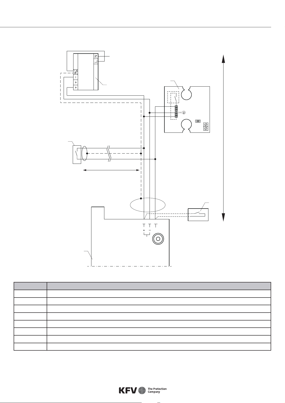
Wiring diagram for type A automated latch release
DSP 30
24V DC
Kl. 4 Fl.
( +24 V DC)
234
24VDC
2
4
3
5
6
7
8
1
No. Description
1 230 V AC supply line (L; N; PE)
2 Power supply
3 Wireless receiver (optional)
4 External unlocking (optional)
5 Line length max. 50 metres (external unlocking)
6 Line length max. 13 metres (from automated latch release to power supply)
7 Internal release push-button (optional)
8 Type A automated latch release
Table des matières
Autres manuels Siegenia-AUBI Serrure de porte


