Shuangdeng Group Co. GFM Series Manuel utilisateur

Statement
The copyright of this document only belongs to Shuangdeng
Group Co.,Ltd.Any excerpt, copy or translation is prohibited without
the written permission of the writer.
Any pirate must be published.
is our registered trademark. The name and trademark of the
product of Shuangdeng Group is our unique mark. Other products
belongs to their respective owners. Without any prior written
consent of Shuangdeng Group or the third party trademark or the
commodity name owners, this manual gives nobody any right to
use the mark appeared in this manual.
This product complies with the design requirement in
environmental protection and human safety. The storage, usage
and discard of this product should be refer to the manual, contract
or relative laws.
For the update and perfection of the product, please understand
that the information in this manual may differ partially from the real
product.
For the latest information, please dial the market hotline.
Foreword
Manual Description
GFM Series VRLA Battery is the product of Shuangdeng Group. GFM Series VRLA Battery
User s Manual is the manual accompanied with the battery. Please read the manual carefully in
advance.
Introduction
GFM Series VRLA Battery User s Manual introduces the technical parameter, principle,
installation dimension and method, and maintenance.
Section 1 Safety introduction containing some watchful safety proceedings during batteries s
installation operation and maintance .
Section 2 Summarization containing GFM series battery model product sampling product
conveying and using ambient requirement parts denomination product specification
and main parameters.
Section 3 Usage and maintenance containing maintenance watchful proceedings charge
method relationship of temperature and capacity relationship of temperature and
cycle life capacity checking switch power parameters setting using requirement
under power off condition maintenance periods and requirements.
It is promised that:
We apply four eye-catching marks to show the special noticed points in operating.
notice caution warning danger: show the special operation
precautions.

Appendix
Chapter 1 Safety Instruction ....................................................................... 26
1.1 Abstract............................................................................................. 26
1.2 Precautions ....................................................................................... 26
Chapter 2 Summary ..................................................................................... 28
2.1 Model Introduction ............................................................................ 28
2.2 Sampling ........................................................................................... 28
2.3 Conveying ......................................................................................... 28
2.4 Storage ............................................................................................. 29
2.5 Dimension and Weight ...................................................................... 29
2.6 Battery Appearance and Each Part Denomination ........................... 30
2.7 Operation Environment and Precaution. ........................................... 31
2.8 Check After Installation ..................................................................... 31
Chapter 3 Operation and Maintenance ...................................................... 35
3.1 Operations ........................................................................................ 35
3.1.1 Precaution ................................................................................ 35
3.1.2 Battery Charging ...................................................................... 35
3.1.3 Temperature Effects the Battery Capacity ................................ 36
3.1.4 Temperature Impact on the Battery Life .................................... 37
3.1.5 Capacity Determination ............................................................ 38
3.1.6 The Parameter Set of the Switch Power Supply ....................... 38
3.1.7 The Application Requirements for Power Supply Interruption
Time .................................................................................................. 40
3.2 Maintenance Period and Requirements ............................................ 40
Operation Instruction of Battery Recharging 42

Chapter 1 Safety Instruction
1.1 Abstract
This chapter introduces about the safety signs and the precautions. Please carefully
read it before operation to ensure safety.
Safety Signs
The safety signs indicate the safety issues that should be conformed to in installation,
operation and maintenance. The safety signs are shown as following Table1.1-1
Table1.1-1 Safety Signs and Meanings
Safety Signs Meaning
Safety Notice
Electric Shock
1.2 Precautions
Before any operation of the equipment, please carefully read all the safety
instructions in this manual to avoid personal injury or equipment damage.
Shuangdeng Group bears no liability to the consequences incurred by violation of the
general safety operation requirement, or violation of the safety standards for designing,
manufacturing and using the equipment.
1. The battery pack has high voltage, so direct contact or indirect contact through wet
objects with any conducting cable may result in vital injury. The battery pack is
energy-storing equipment, so never short-circuit the battery pack during operation
and maintenance in any way.
2. Do not wear watch, hand chain, bracelet, ring and other conductive objects during
operation.
3. Only qualified and professional personnel are allowed to install, operate and maintain
the equipment.
4. Do use special tools.

Do use special tools, instead of common tools during electrical connections. In
addition, keep the tools in good insulation condition (e.g. wrap insulating tape around
the bare metal parts) before using them to avoid short circuit and personal injury
caused by tool contact with any live objects.
5. Using the batteries of the same model
Use batteries of the same model in the same set. Using different models in the same
set will damage the equipment.
6. Fire hazard
During battery installation, make sure to fix the connecting terminals of the
conducting wire tight, and keep the output terminals of the batteries clean. Otherwise,
it may lead to a high temperature of battery terminals and even to spark/fire.
7. Operation regulation
Before battery operation, read the safety precaution/instruction, and the operation
instructions, especially the battery interconnection instructions.
Substandard operation will cause danger. Prevent battery short circuit and
prevent battery electrolyte from flowing out. Overflowed electrolyte is a latent danger
and it will erode the metal object and circuit board, thus damaging the equipment and
causing short circuit of the circuit board.
8. The Operation Environment
The battery should be kept far away from fire, organic solution; avoid direct sunshine
and the temperature should be the same of the same set.
Chapter 2 Summary
Abstract
product sampling product
conveying and using ambient requirement parts denomination product specification and
main parameters.
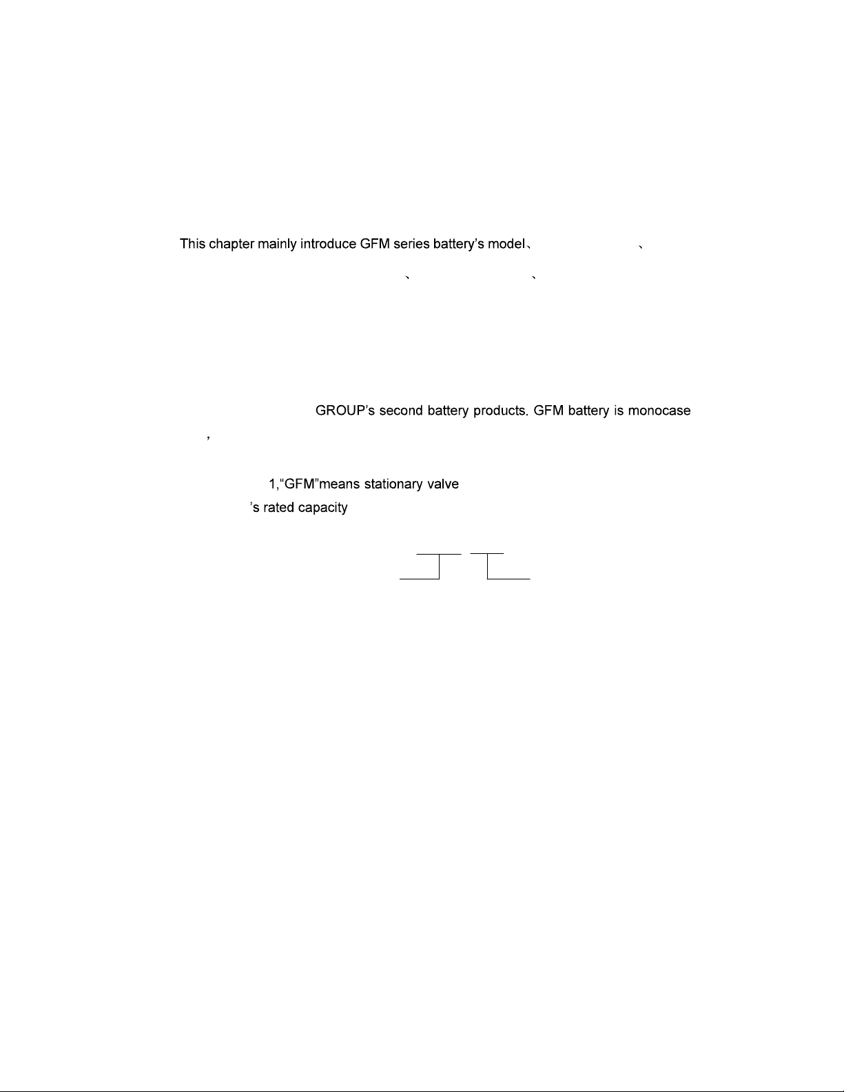
2.1 Model Introduction
GFM series valve-regulated lead-acid battery(following called GFM battery for short)
belong to SHUANGDENG
structure rated voltage per cell is 2V. Take GFM-500 for example, its mean as fig.2.1-1
showing.
In the fig.2.1- -regulated lead-acid battery, the figure
presents battery .
GFM-500
rated capacity C10
unit:Ah
valve-regulated
lead-acid battery
Fig.2.1-1 GFM-500 battery type and description
2.2 Sampling
Choosing batteries should consider use frequency, discharge current, discharge
time and so on. The capacity should be a bit larger to prevent battery from damage
caused by over-discharge or larger current discharge. Discharge current often be
controlled less than 0.1C10A.
2.3 Conveying
Terminal protection is well done, the coping of the battery cannot suffer the pressure,
safety valve cannot become flexible, and short circuit is prohibited when batteries are
conveyed. Batteries should stand up at the time of transporting and cannot set upside
down, roll, throw, bump, insolate or drench during conveying.
2.4 Storage
1. Batteries can be stored in the environment of 0-35°C before installation. The storage
time is usually 3-6months. Batteries should be charged if the storage time exceeds 6
months.
2. Batteries should be kept in the dry, clean and ventilated environment. They cannot be
kept in the environment of radiation, organic solvent and corrosive gas. They should
be kept away from fire and avoid sun irradiation.
3. Batteries should stand up, safety valve cannot become flexible and batteries without
package box cannot be overlapped.
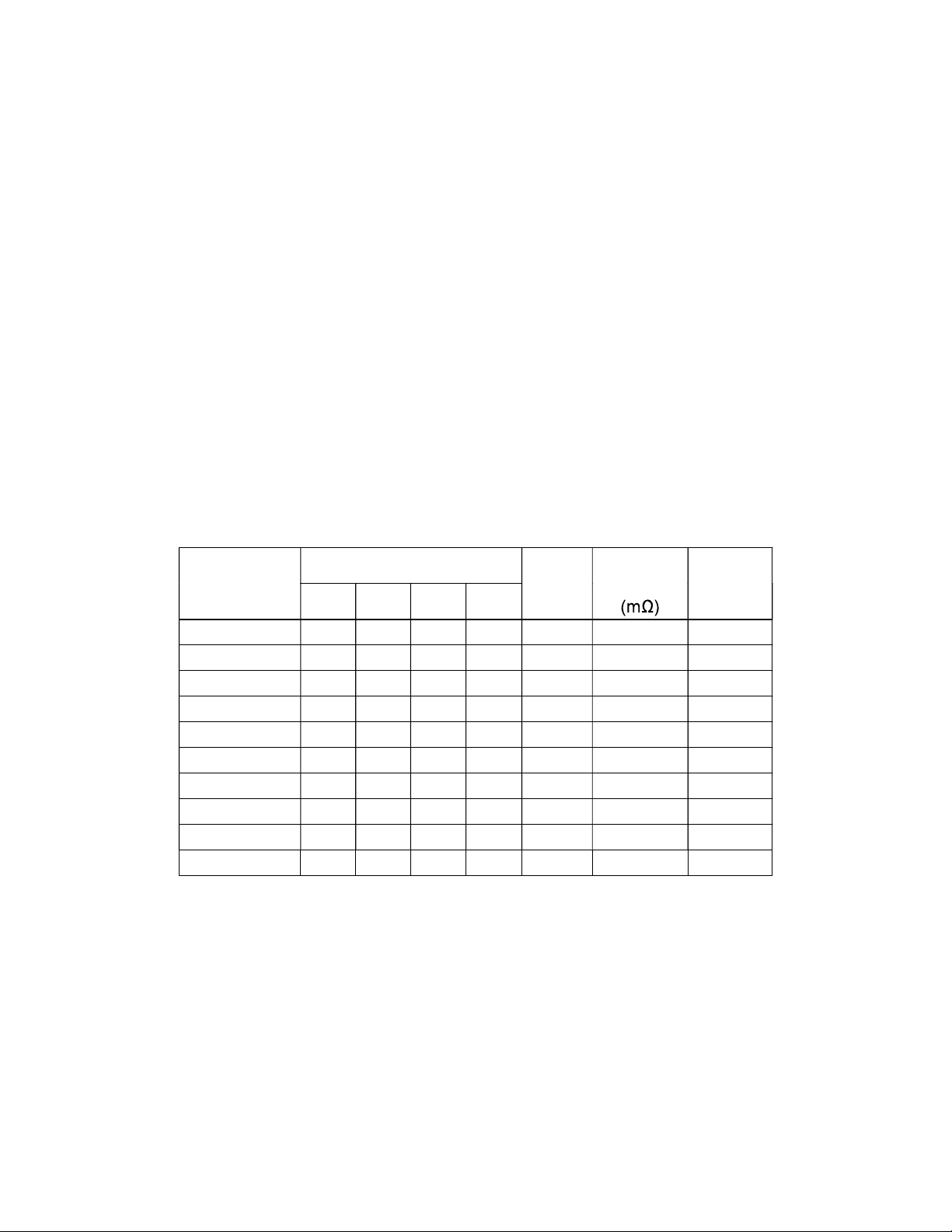
2.5 Dimension and Weight
Table2.5-1 Battery parameters
Type
Dimensions(mm) Weight
(Kg)
Internal
resistance
Terminal
L W H TH
GFM-200 90 181 346 365 12.5 0.90 M8
GFM-300 124 181 346 365 17.6 0.60 M8
GFM-400 158 181 346 365 23.0 0.51 M8
GFM-500 191 181 346 365 28.6 0.41 M8
GFM-600 225 181 346 365 33.2 0.39 M8
GFM-800 303 181 346 365 45.4 0.38 M8
GFM-1000 370 181 346 365 56.5 0.36 M8
GFM-1600 318 363 369 388 98.0 0.20 M8
GFM-2000 385 363 369 388 117.0 0.18 M8
GFM-3000 568 363 369 388 178.0 0.17 M8
H
TH
H
TH
H
H
TH TH
Fig.2.5-1 Battery figuration
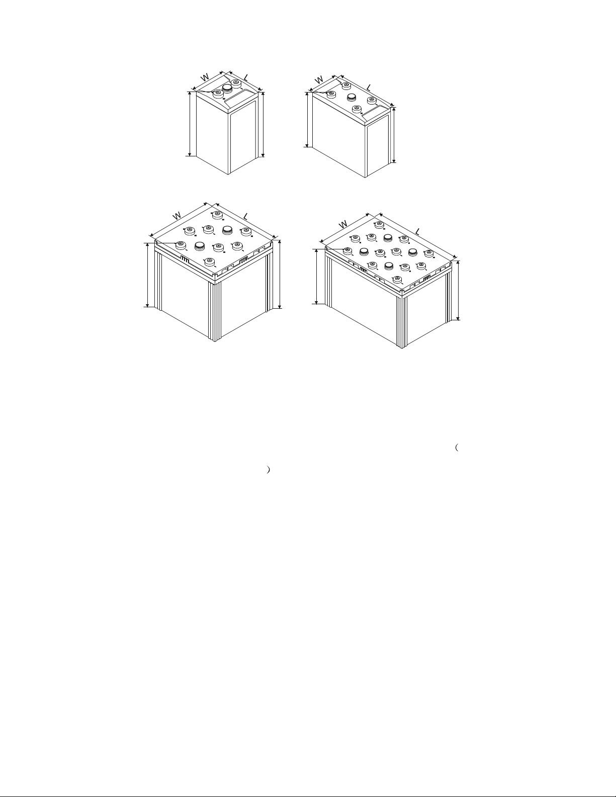
2.6 Battery Appearance and Each Part Denomination
Following is the appearance and each part denomination of GFM battery take
GFM-500 for example, as fig. 2.6-1
GFM-200~600 GFM-800~1000
GFM-3000
GFM-1600~2000
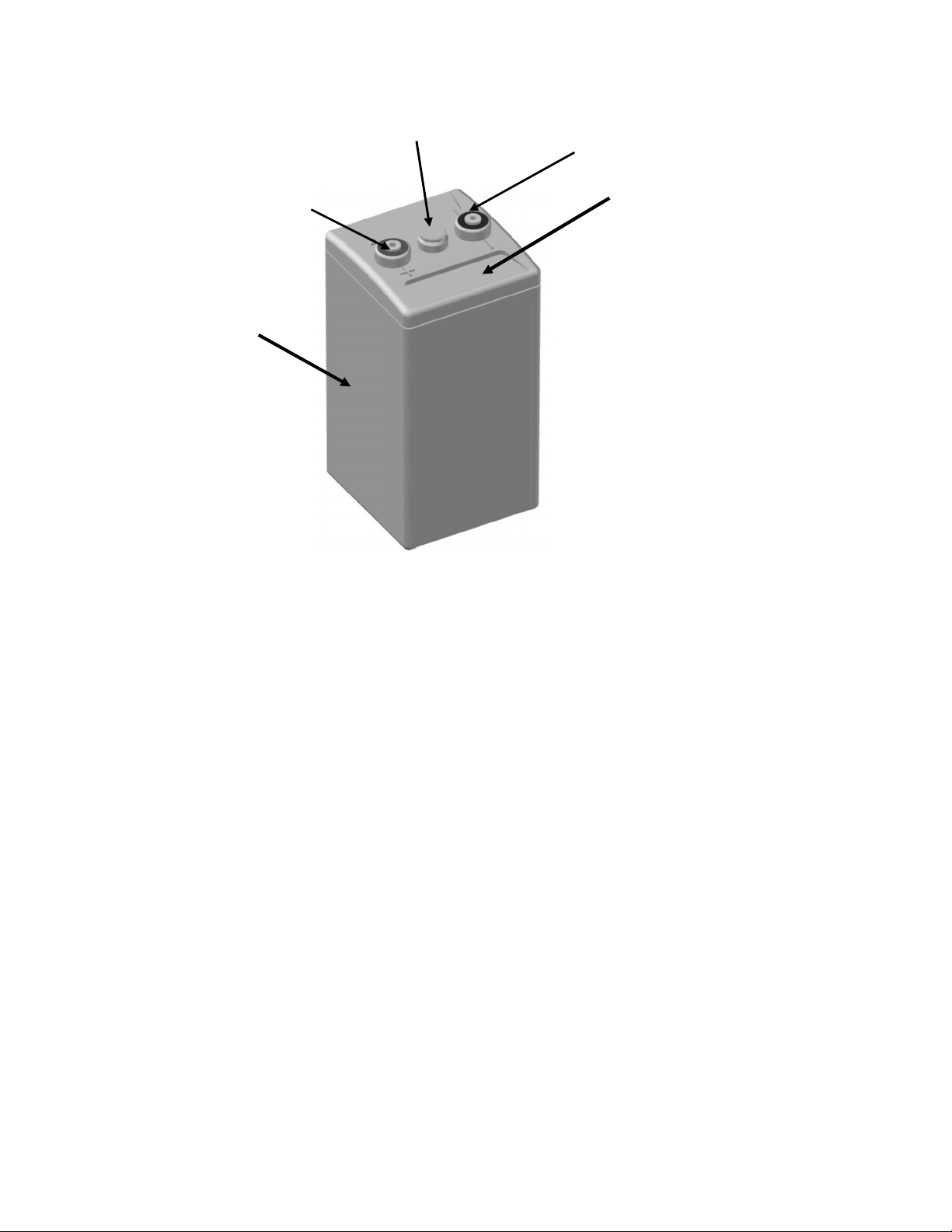
Fig.2.6-1 Battery figuration and accessories
2.7 Operation Environment and Precaution.
1. The battery servicing surroundings should be dry, clean and airy, without large
quantity of irradiation, infrared ray radiation, organic solvents and corrosive gas, and
avoided the direct sun shining. the temperature not exceed 35°C.
2. The ventilation hole of the heater or air-conditioner should not directly face the battery,
and the temperature difference of the each part of the battery should not be higher
than 3°C, and using the infrared ray thermometer to determine the each part
temperature of the battery is suggested.
3. The battery can be installed with the battery cabinet or shelf provided by the
manufacturer. If the battery is installed in the storied buildings, the load requirements
should be inquired from the construction department. The earthquake-preventing
supporting shelf which is fixed with ground foot bolt should be designed in order to
diffuse the stress in the district whose anti-earthquake intensity is more than 7
degree.
safety valve
positive terminal
container
negative terminal
cover

4. In order to avoid increasing the circuitry voltage decrease, the battery modules
should be near the load, and the cables, copper terminals and connecting wires
selected should be suitable. When the batteries are used by the way of
parallel-connection, the circuitry voltage decrease should be same to some extent to
the best of one's best ability, and the fuses should also be equipped in every battery
module.
5. The total voltage of the battery modules is comparatively higher, i.e., the danger of
electric shock exists. Therefore, the insulation tools should be used and the
protection gloves should be put on when installing or removing the cable, copper
terminals and connection wires etc.
6. Dirty contact or loosened connection will possibly lead to the temperature increase in
the part of the battery terminal, then spark will be produced, which will probably result
in fire. Thus, the cable, copper terminals, connection wires, and the battery terminals
should be kept clean and the connection should be fastened during the installation of
the battery. Single battery should be serially connected with stainless steel bolt,
copper terminals (connection wires and cables) electrodeposited with tin, and flat
gasket. And the bolt must be fastened (Wring moment is no less than 15N·m).
7. After the installation, carefully examine the total voltage, open circuit voltage per cell,
the polarity. Check to see if the supervising parameters in the switch power monitor
unit consist with the operation and maintenance manual (float charge voltage,
equalization charge voltage, equalization charging time and period, charge current
limit, equalization charge current turned to float charge, float charge current turned to
equalization charge current, temperature compensation value, the recovery voltage
of the battery and so on.).
8. Check to see if the switch power has equipped with the temperature sensor, which
should be installed in the center of the big side of the battery.
9. The resistance between the output terminal and the cabinet (shelf) should be
carefully checked in order to confirm the correctness of the installation and settings
after the battery system is installed.
Ce manuel convient aux modèles suivants
10
Table des matières


