SHS HT7 Series Manuel utilisateur

S.H.S. s.r.l. Via F.lli Rosselli, 29 20027 Rescaldina (MI) – ITALY Tel. +39 0331 466918 Fax. +39 0331 466147 www.shsitalia.it
User Guide
STEPPING MOTOR DRIVE
Series
HT7
Models
PROFINET
HT7_PROFINET_re 8_eng

Safety notes
The SHS automation products should be handled, installed and maintained by quali ied personnel trained
on installation o automation components, and only or the purposes described in the user manual.
Installers must pay particular attention to the potential risks caused by mechanical and electrical
equipment.
It is very important that applications and installations meet all applicable safety requirements.
Each installer has an obligation to take responsibility to verify their knowledge and understanding of all applicable
safety standards.
Any use which does not meet the sa ety requirements can damage equipment and injure the user.
SHS s.r.l. does not consider itsel responsible or, and assumes no liability or damage caused by handling
products and / or improperly installed, or in cases where the customer has allowed, or executed,
modi ications and / or repairs not authorized by SHS s.r.l.
The SHS drives are devices for automation high performance capable of generating rapid movements and high
forces.
Pay high attention especially during installation and application development.
Only use equipment properly sized for the application..
The SHS devices are considered components for automation and are sold as finished products to be installed only
by qualified personnel and in accordance with all local safety regulations.
The technicians must be able to recognize possible dangers that may result from programming by changing
parameter values and generally by the mechanical electrical and electronic.
SHS s.r.l. recommends to always follow basic safety rules. Failure to heed them can result in injury to persons and /
or property.
General precautions:
This manual is subject to change due to product improvement specification changes or improvements of the
manual
SHS s.r.l. is not responsible for damage to property and / or persons caused by faulty installation and / or
unauthorized modifications of the product.
The damaged drive systems must not be installed or put into operation in order to avoid injury persons
and damage to property. Changes or modifications made to the drive systems is prohibited and It
involves the extinction of any right to warranty or of any obligation of responsibility.
2
www.shsitalia.it info:[email protected]

www.shsitalia.it info:[email protected]
Index
TECHNICAL DATA 4
1.1 Power supply / Motor Connector 4
1.2 FIELDBUS Connector 4
1.3 Input/Output Connectors 5
1.4 DIP-SWITCH and Ethernet Connectors 6
1.5 Status LEDS 6
1.6 Protection / Display messages 7
1.7 Parameters setting 8
1.8 Mechanical dimension 9
CONNECTION 10
2.1 Installation note 10
2.2 AC Power Supply 10
2.3 DC Power Supply 12
2.4 Input / Outputs 13
2.5 Digital Inputs 14
2.6 Digital Outputs 14
2.7 Encoder Inputs 15
2.8 16
OPERATING MODE 16
3.1 PROFINET Protocol 17
3.2 Data communication ia PROFINET 17
3.3 PROFINET control bits 19
3.4 ZSW bits positioning timing 20
3.5 Parameters 23
HT7 MODELS CODE 27
Analog Inputs/ Outputs
3
www.shsitalia.it info:[email protected]
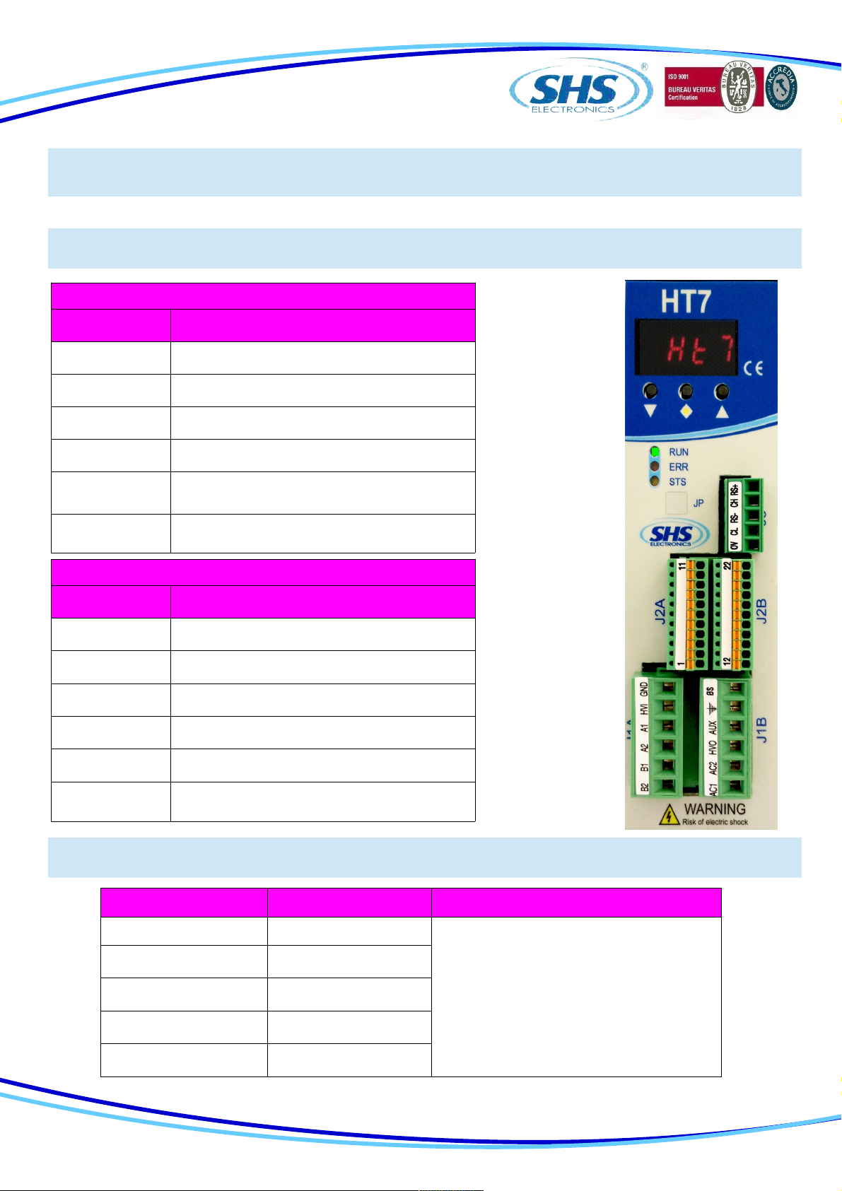
1. TECHNICAL DATA
1.2 FIELDBUS Conne tor
1.1 Power supply / Motor onne tor
J1A ( Le t )
SIGNAL FUNCTION
B2 Phase B2 of the motor
B1 Phase B1 of the motor
A2 Phase A2 of the motor
A1 Phase A1 of the motor
HVI Power supply input DC
(connect to HV0 or use as input DC power)
GND 0V power supply
J1B ( Right )
SIGNAL FUNCTION
AC1 Power supply Vac
AC2 Power supply Vac
HV0 Rectified output
AUX Logic power supply input 24Vdc
SHIELD Shield
0S 0V power supply Aux
J3 SIGNAL FUNCTION
1 0V
2 CL (CANL)
3 RS- (RS485-) Used only upgrade firmware
4 CH (CANH)
5 RS+ (RS485+)
4
www.shsitalia.it info:[email protected]
1.3 Input / Output Conne tors
J2A (Left) SIGNAL FUNCTION
1 ENC_AH Encoder A+
2 ENC_AL Encoder A-
3 ENC_BH Encoder B+
4 ENC_BL Encoder B-
5 ENC_ZH Encoder Z+
6 ENC_ZL Encoder Z-
7 ENC_COM Encoder common (don't se in differential
mode)
8 ENA/DIS Input ENABLE/DISABLE
9 IN3 Input IN3 – (CURRENT REDUCTION)
10 IN2 Input IN2 - (DIRECTION)
11 IN1 Input IN1 – (STEP IN)
J2B (Right) SIGNAL FUNCTION
12 OUT_COM Output common (OUT1 OUT2 OUT3)
13 OUT1 Output OUT1 - (default motor run)
14 OUT2 Output OUT2 - (default Drive Ready)
15 OUT3 Output OUT3 - (default unused)
16 IN_COM Input common (IN1 IN2 IN3 ENA/DIS)
17 AN_IN0 Analog Input IN0
18 AN_IN1 Analog Input IN1
19 AN_IN2 Analog Input IN2
20 AN_OUT Analog Output
21 GND_SIGNAL 0V (relative at EXT_12V AN_IN AN_OUT)
22 EXT_12V Output +12V (relative at GND_SIGNAL)
5
www.shsitalia.it info:[email protected]
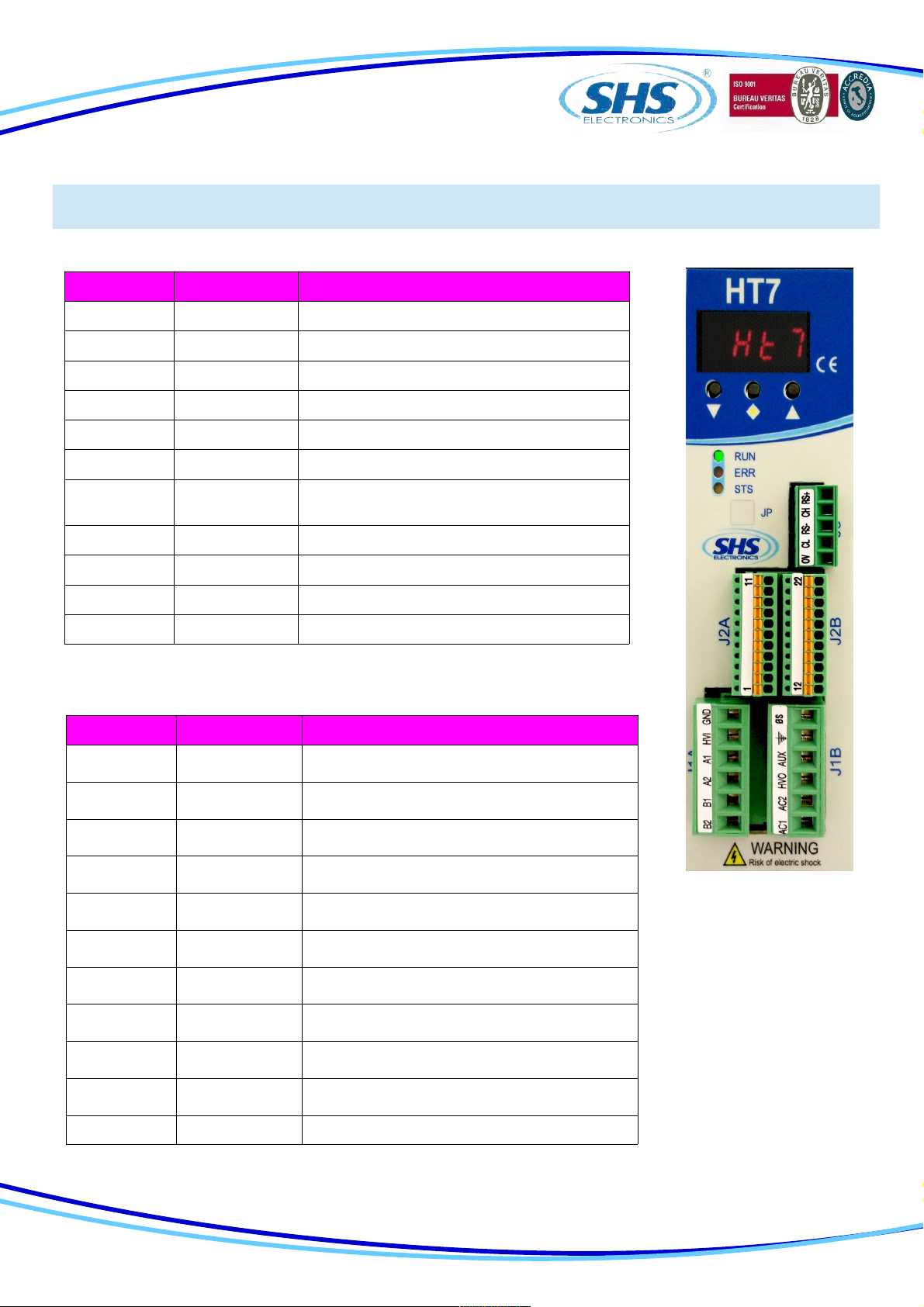
1.4 DIP SWITCH
1.5 Status LEDS
DIP1 ON OFF
1 Insert termination CAN Not used
2 Insert termination RS485 Not used
3 Not used Not used
4 Input function En / Dis = ENABLE Input function En / Dis = DISABLE
Phisical
Features Connection Type Cable /
Transmission type Speed Max Cable
Lenght
Electrical RJ45 Connector
100base-TX Shield
cable CAT5 IEEE
802.3
100Mbit/s full
duplex 100 mt
LED FUNCTION
RUN
Drive OK Light ON
Drive Error Light OFF
ERR
Drive Error Light OFF
Drive OK Light ON
STS
Drive OK Light fast blinking
Drive Error Light slow blinking
Only HT7xx PN, EC, EI model is supplied of double RJ45 interface ( upper pictures ).
The RJ45 connections can be used interchangeably in PN and EI model.
6
www.shsitalia.it info:[email protected]
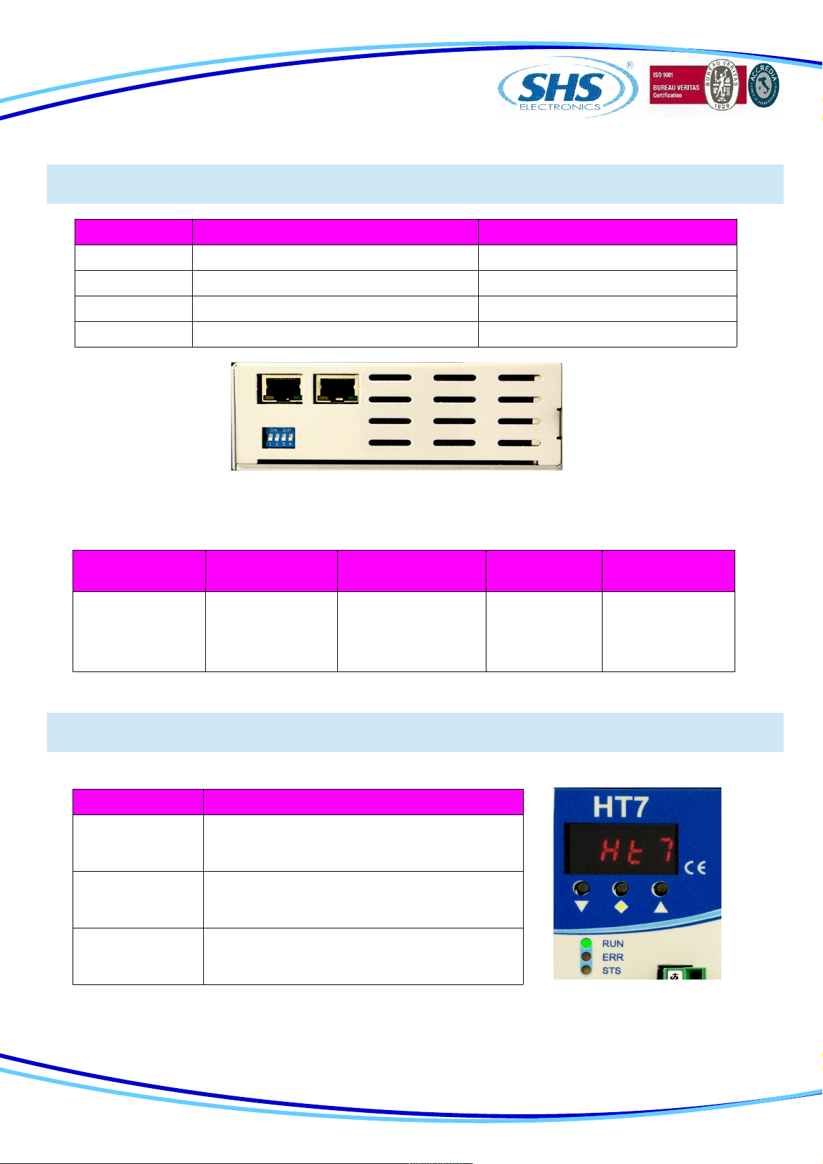
1.6 Prote tion / Display messages
DISPLAY DESCRIPTION
rdY Drive OK at STOP motor
run Motor in movement
dIS Drive DISABLE
ocur Overcurrent Error
tenP Overtemperature Error
uuoL Undervoltage Error
ouoL Overvoltage Error
rSt Reset phase
0net No connected
Dri e is pro ided with protections against o ertemperature, o er oltage, under oltage, short-circuits among
outputs and among outputs and the positi e power pole, no-phase motor connection.
If one of the mentioned conditions occurs, dri e disables the power bridge and shows an error condition on
the display.
To restore o ercurrent protection tou must restart the unit.
The decimal point to the left indicates the status RX, while the one on the right indicates the status of the
communication interface TX.
7
www.shsitalia.it info:[email protected]
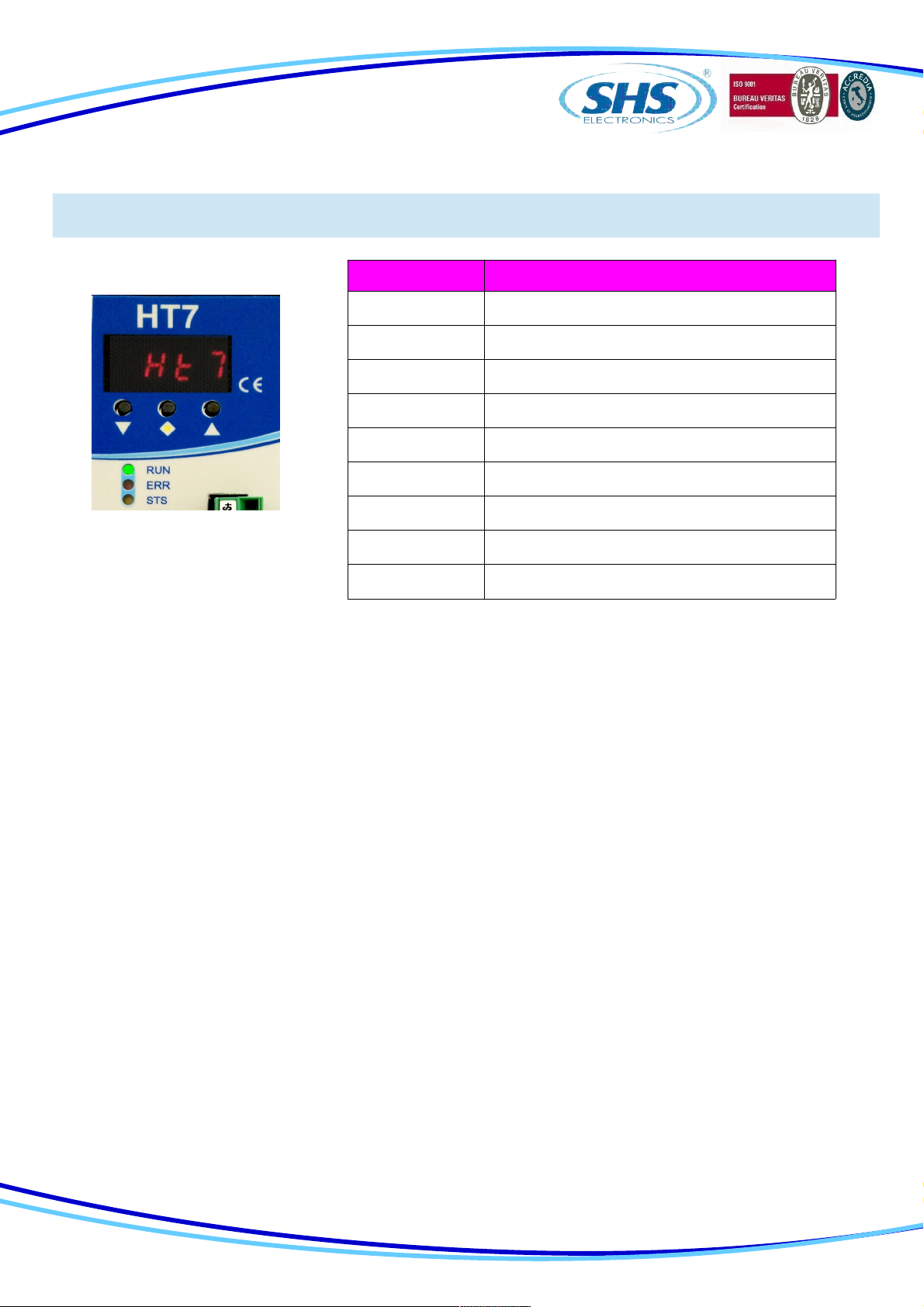
1.7 Parameters setting
PARAMETER FUNCTION
p001
0par: when this parameter is stored all
parameters will be set to default value and it will
appear “rst” then restart the driver
p003 Current setting [A]
p006 Setting step resolution ( 1/2 ... 1/20 )
p00 Setting stand-by current ( 0 25 50 100% )
p008 Setting parameter resonance1 reduction
( fd0 ... fd4 )
p009 Setting parameter resonance2 reduction ( small
big )
p010 Setting wave mode ( wav0 wav1 )
p011 Setting to operate high frequency
p013 Setting toggle bit ( 0 - 1 )
p014 Enable refresh for the last polled parameter
p015 Enable refresh status word
p016 Motor Stopped when the driver communication
fault
By using the buttons below the display (hereinafter referred to as [\/] , [<>], [/\] ) you can parameterize the dri e:
To access to main menù, press [\/] + [<>] , it will isualized “ menu ” for 1 sec, after the parameter “ p001 ”
From the main menu to select the parameter to be changed press the button [\/] or [/\].
From main menù to isualize the actual alue of parameter press [<>].
From the parameter to change the alue press [\/] or [/\]
From the parameter to store the alue press the button [<>] for 1 sec and it will appear “ memo ”
From the parameter to come back at main menù without modify any conditions, press [<>] less than 1 sec (don’t will
appear “ memo”).
From the main menù to go out press [<>] + [/\].
8
www.shsitalia.it info:[email protected]
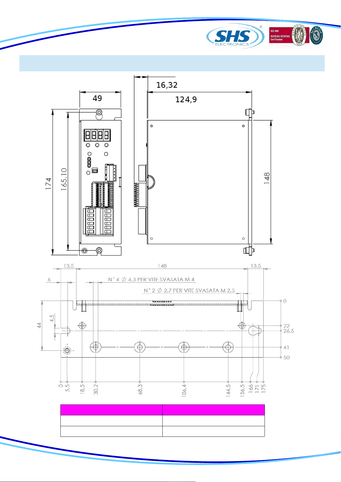
1.8 Me hani al dimension
MODEL HT7 xx- WEIGHT [ gr ]
WS-MB-CO-PB 655
PN-EC-EI 720
9
www.shsitalia.it info:[email protected]
2. CONNECTIONS
2.1 INSTALLATION NOTES
ATTENTION
2.2 AC Power Supply
Unit HT710 HT720 HT730 HT740
Vac nom [V] From 18 to 60 From 18 to 60 From 18 to 60 From 18 to 90
Vac max [V] 75 75 75 110
Vac min [V] 15 15 15 15
I max [A] 4 7 12 12
I min [A] 1 1 1 1
Operation
Temperature [°C] 0 - 45 0 - 45 0 - 45 0 - 45
Vdc aux [V] 24 24 24 24
DANGER OF ELECTRICAL SHOCK
ONLY QUALIFIED ERSONNEL SHOULD WORK ON THIS EQUI MENT. DISCONNECT ALL OWER
BEFORE WORKING ON EQUI MENT. DANGEROUS VOLTAGES MAY EXIST AFTER OWER IS
REMOVED! BEFORE WORKING ON EQUI MENT CHECK DC BUS VOLTAGE OF
DRIVES EACH TIME OWER IS REMOVED.
The transformer power is =Vac*(Inf(tot) + 1)
Where is VA power, Vac is secondary voltage in Volts and Inf(tot) is the sum of all nominal currents set
in all the dri e to be supplied.
NOTE: use a transformer with an isolated secondary, don’t connect the secondary at ground.
Vac nom : Range alue of oltage by which the dri e can be powered.
Vac max: Opertati e Maximum oltage. O er this limit, the protection of maximum oltage inhibits the
dri e.
Vac min: Operati e Minimum oltage. Under this limit, the protection of minimum oltage inhibits the
dri e.
I max: Maximum alue of phase current.
I min: Minimum alue of phase current.
Operating temperature: For any temperature o er 45°C and any current o er 6A a forced entilation is
necessary.
Vdc aux: Logic power supply.
10
Autres manuels pour HT7 Series
2
Table des matières
Autres manuels SHS Entraînement CC


Manuels Entraînement CC populaires d'autres marques

Vincent Associates
Vincent Associates UNIBLITZ ED12DSS Manuel utilisateur

EKSMA OPTICS
EKSMA OPTICS DQ-100-4 Manuel de la liste des pièces

Chamberlain Garog
Chamberlain Garog D Series Manuel utilisateur

Parker
Parker PDS Series Manuel utilisateur

Festo
Festo DGC G Series Guide de configuration

Binks
Binks QS-5012-1-CE Manuel utilisateur


