3
1Table of contents
1TABLE OF CONTENTS................................................................................................... 3
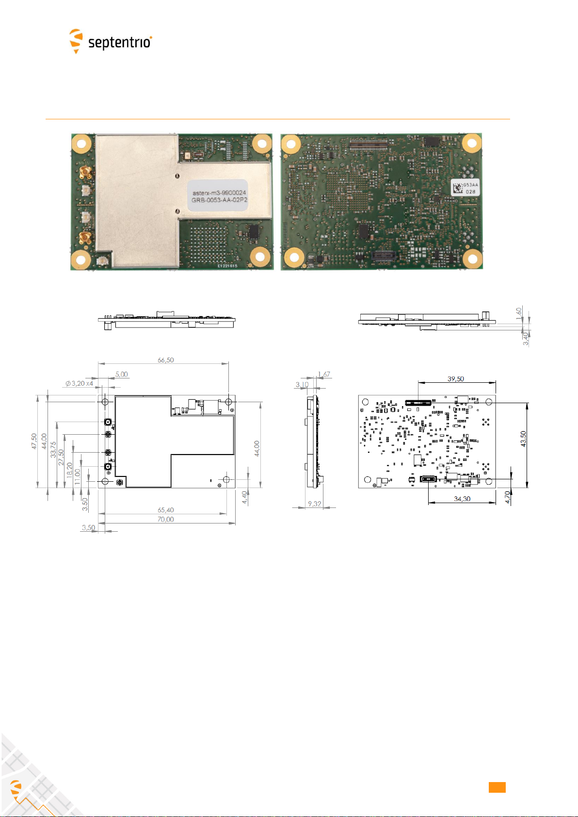
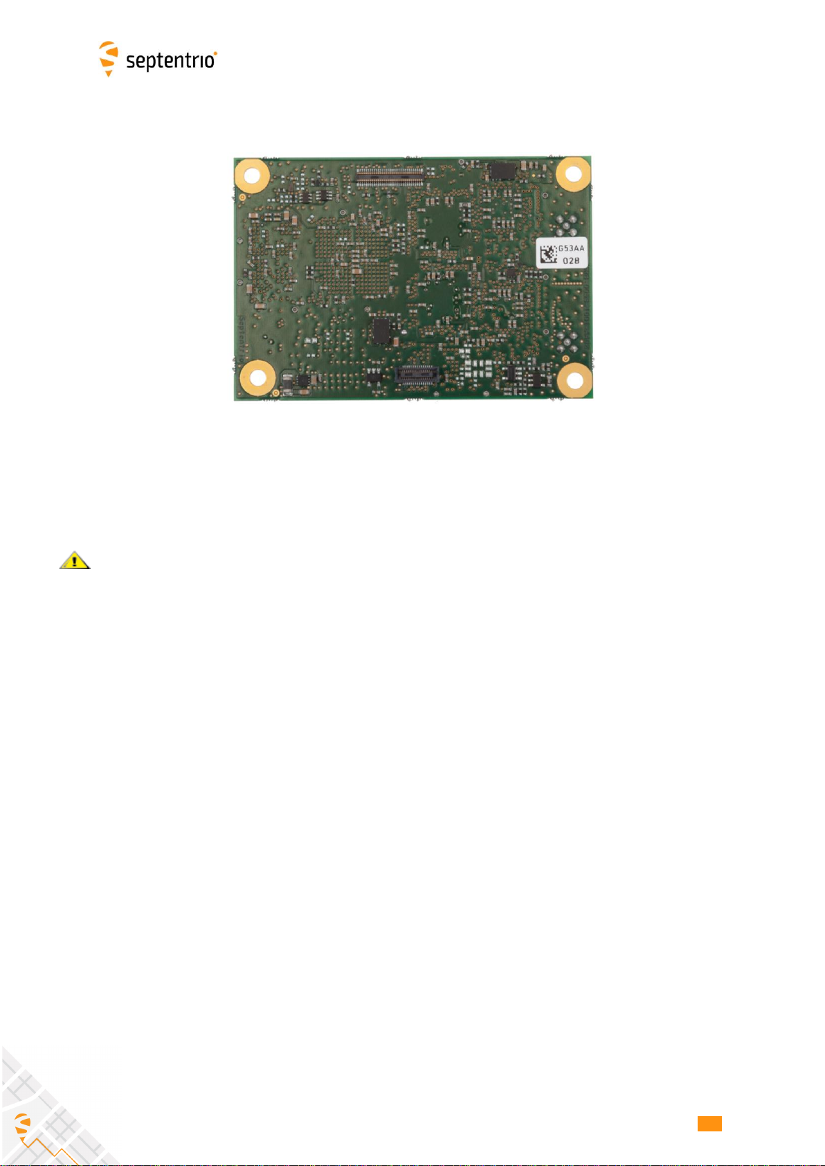
2ASTERX-M3 OEM .......................................................................................................... 6
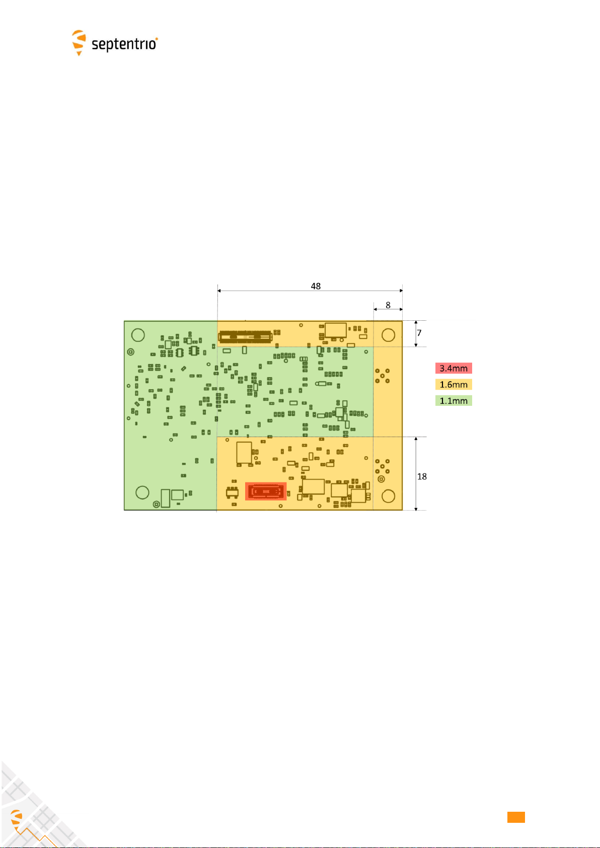
2.1 Mounting .................................................................................................................. 7
2.2 Environmental ......................................................................................................... 7
2.3 Power and Power Consumption ............................................................................ 7
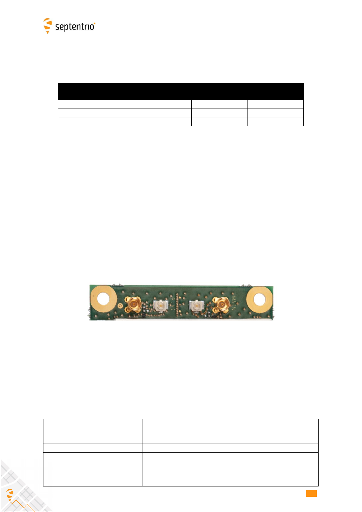
2.4 RF Interface.............................................................................................................. 8
2.4.1 Electrical Specifications .......................................................................................... 8
2.5 I/O Connectors....................................................................................................... 10
2.5.1 30-pin Connector.................................................................................................. 11
2.5.2 60-pin connector................................................................................................... 12
2.6 External Frequency Reference Input (REF IN).................................................... 14
2.7 Frequency Reference Output (REF OUT)............................................................. 14
2.8 Event/TimeSync Inputs......................................................................................... 14
2.9 General Purpose Output (GPx) ............................................................................ 15
2.10 Standby Mode ........................................................................................................ 15
2.11 SD Memory Card Usage ........................................................................................ 16
2.12 USB Interface ......................................................................................................... 17
2.13 Ethernet.................................................................................................................. 17
3ROBOTICS INTERFACE BOARD .................................................................................. 19
3.1 Mechanical Drawings............................................................................................ 20
3.2 USB Dev................................................................................................................... 20
3.3 44-pin Header......................................................................................................... 21
3.4 LEDs......................................................................................................................... 22
3.5 Log Button Header ................................................................................................ 23
3.6 PPS/Event Header.................................................................................................. 23
3.7 Power Supply Options........................................................................................... 23