SCI ERV-24-HC11 Instructions d'utilisation

Technician
Settings
ER
V
-24-HC11
With FanCycler®
Pipersville, PA 18947 USA
Phone: 215-766 1487 - Fax: 215-766 1493
Cat. P048013
Rev. 2.1 12.04

2
Please read this manual carefully before installation and use.
Index
Introduction 1
Options and Accessories 2
Installation Instructions 3
Wiring connections 4
DIP Switch and Jumpers explanation 5
Remote Sensor connections 6
Advanced Setup 7
Fan Cycling Configuration 8
Ventilation Damper Cycling 9
Fan over-run after cooling status 10
Fan cycling at night in heating mode status 11
Circulator pump status 12
Data Storage for System Diagnostics 13
Locking the thermostat’s buttons 14
Temperature Offset settings 15
Troubleshooting for the technician 16

3
1. Introduction
Advanced Ventilation Features of the ERV-24-HC11 thermostat with FanCycler®
Protected by one or more of the following patents:
US 5,547,017; 5,881,806; 6,431,268; CA 2,245,135
The ERV-24-HC11 thermostat with FanCycler®has enhanced features to compliment controlled
mechanical ventilation systems. These features were configured for use by your installing technician.
(For more information please refer to the technician manual or visit www.scillc.com and
www.fancycler.com).
A brief description follows:
FAN CYCLING CONFIGURATION — The purpose of fan-cycling is to assure that the central air handler
fan will run just enough to distribute ventilation air and mix the air evenly throughout the house when
there is no demand for the heating or cooling operation to activate. Rather than cycle the fan
continuously, or intermittently by a timer (which doesn't consider prior operating conditions), the
FanCycler method saves energy, and wear and tear on equipment by operating the fan only when
necessary.
VENTILATION DAMPER CYCLING — The purpose of cycling the ventilation damper is to limit the
possibility of over-ventilation that would cause unnecessary space-conditioning energy to be used. The
damper will automatically close when the programmed ventilation requirement has been met.

4
2. Options and Accessories
Remote sensor option:
• RS01: for remote temperature sensing (1 required); for averaging temperature at 4
locations (4 required) – the thermostat will control on the average temperature of all 4
locations
• RS02: for averaging temperature at 2 locations (2 required) – the thermostat will
control on the average temperature of both locations
For details on where to purchase accessories, please contact SCI for your nearest
location or visit our web site at www.scillc.com
3. Installation Instructions
Separate the front panel from back panel by depressing the
tongue located in the top of the unit.
Pull the back panel out.
Line the back panel up against the wall or flat surface. Install
three screws as required.

5
On/Off Select Prog
Cool
Heat
Auto
Fan
Setting
Make electrical connections as shown on enclosed electrical
wiring diagram. (Next page) Verify that you have 24 VAC
between terminals C and Rh/Rc.
Install the cover to the back panel; first the two tabs on the
bottom and then the top tongue.
Push until tight against the wall. Wait for 15 seconds for the LCD
display to appear (completion of power circuit charging and for
self-diagnostics).
4. Wiring Connections
Switch Function Switch Function
Rc 24 VAC RED T Remote temperature sensor
Rh 24 VAC RED (jumpered to Rc) T Remote temperature sensor
C 24 VAC Common from transformer FD Fresh air damper – power open
W1 Heating (one stage) G Fan
Y1 Cooling (one stage)
Please reference the stickers placed on top of screw terminal connectors on the wall plate when
wiring the unit (the designated terminals on the printed circuit board are for internal (factory) use
only).
“T” Terminals can be used in any system configuration when a SCI remote sensor is connected
and the DIP switch is correctly configured.
6
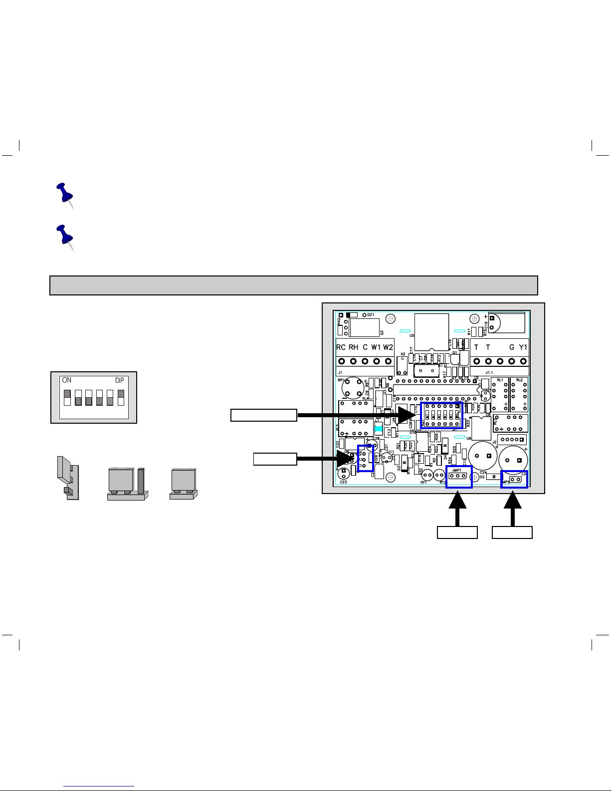
JMP10 JMP1 JMP2
A
B
A B
DIP switch
JMP10
JMP 1 JMP 2
Y2
FD
The Rc/Rh terminals are bridged at the factory for a one transformer application. In the case of
a two transformer application, you must remove the bridge and connect the individual
transformers to Rc (cool) and Rh (heat).
FD – Fresh-Air Damper connection - 24Vac/1Amp. The damper type must be Power Open,
Spring Close.
5. DIP Switch and Jumpers Configuration
5.1 The DIP switch is located in the middle of
the board as shown in the drawing. (Inside
the thermostat)
Default DIP Switch setting from factory
Default Jumpers position from factory
1 2 3 4 5 6

7
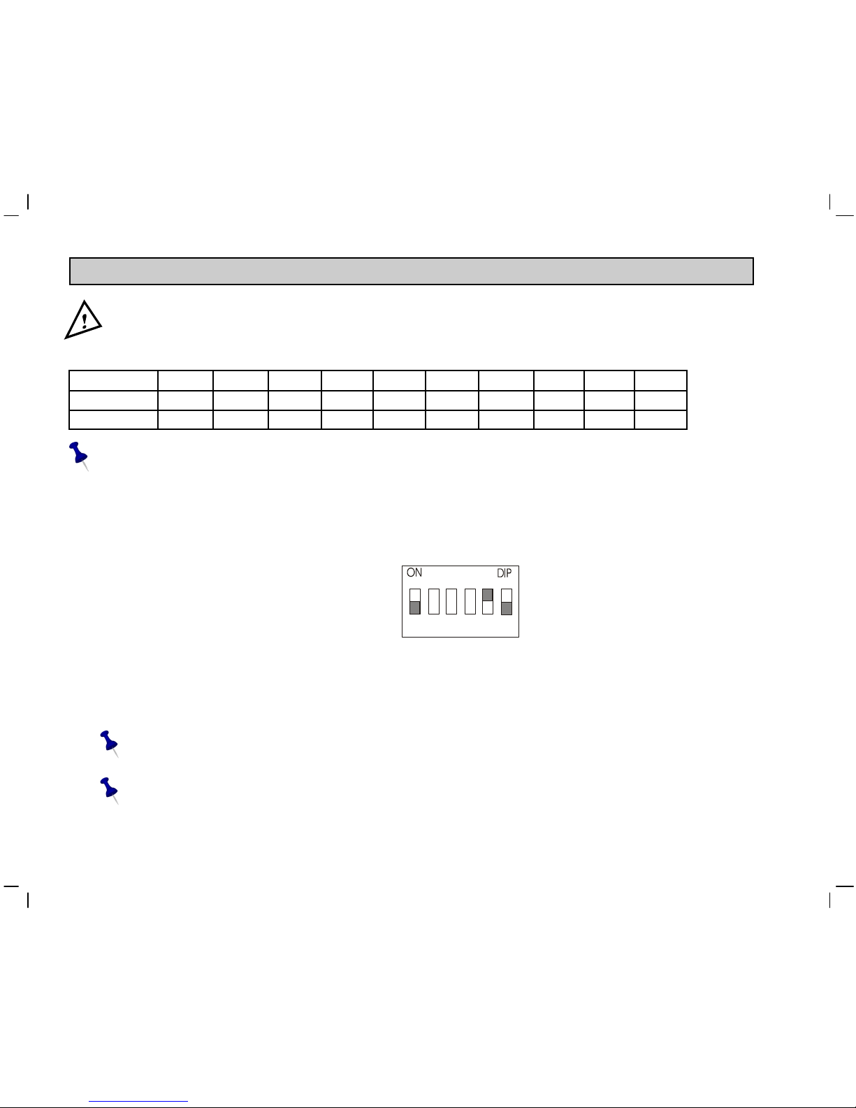
Table 5.1 – DIP switch selection
DIP Switch settings
FUNCTION 1 2 3 4 5 6
Internal temp. sensor1ON x x x OFF ON
Remote temp. sensor OFF x x x ON OFF
Electric1x x OFF x x x
Oil/Gas x x ON x x x
3 min. compressor delay1x x x OFF x x
No compressor delay x x x ON2x x
Programmable1x OFF x x x x
Non-Programmable x ON x x x x
x = Disregard
1 = Factory Defaults
2 = FOR TEST ONLY
5.2 DIP Switch Operation
• The DIP switch has 6 pins.
• Each pin can be ON (top) or OFF (bottom). In the picture, pins 1 and 6 are ON, and pins 2 to 5 are OFF
5.3 Fan Explanation (DIP switch 3)
• Fan control "electric”
Fan will activate immediately with heating and cooling.
• Fan control "oil/gas”
Fan will activate immediately with cooling only. Fan will not be activated by the thermostat for heating.
Heating unit will activate the fan in AUTOFAN mode.

8
A B
A
B
5.4 Jumpers explanation
Jumper 1: Complete Reset of the unit.
For complete reset:
• Move JMP1 to position B.
• Wait 15 seconds.
• Return JMP1 to position A.
JMP1 Default from factory:
Jumper 2: NOT IN USE.
JMP2 Default from factory:
Leave it closed!
Jumper 10: Enable or disable Auto change-over capability
• Enable Auto change-over – JMP10 in position A (default from factory).
• Disable Auto change-over – JMP10 in position B.
Default from factory:
9
6. Remote temperature sensor connections – (optional)
Important! The remote temperature sensor must be SCI type.
Table 6.1 - N.TC. Sensor: Temperature ~ Resistance Characteristics
Temp °C 7.2 10.0 12.8 15.6 18.3 21.1 23.9 26.7 29.4 32.2
Temp °F 45 50 55 60 65 70 75 80 85 90
Res. k 115.8 100.9 88.1 77.1 67.7 59.6 52.5 46.4 41.2 36.6
The default from factory is INTERNAL SENSOR.
6.1 Remote temperature sensor switch configuration
1. Move DIP switches 1,5 and 6 as in the picture. (See Table 5.1 for setting
Switches 2,3 and 4.)
Switch 1 - OFF
Switch 5 - ON
Switch 6 – OFF
2. Connect the temperature sensor leads to the T-T terminals.
3. Reconnect the front half of the thermostat to the base (applies 24Vac power).
4. Verify that the displayed temperature responds to the remote sensor.
The wire length for the remote sensor can be up to 100 feet (30 meters) with standard
thermostat cable (not less than 22 gauge).
If the distance is greater than 100 feet then the wire MUST be shielded type, 20-22 gauge,
twisted pair.
1 2 3 4 5 6

10
6.1.2 Remote sensor wiring configurations
1. Connection of one remote sensor (RS01)
2. Connection of two remote sensors for average measuring (2XRS02)
RS01
THERMOSTAT T
T
mount in acceptable
location for
temperature sensor
RS02
THERMOSTAT T
T
RS02 mount in acceptable
location for
temperature sensor
Autres manuels pour ERV-24-HC11
1
Table des matières
Autres manuels SCI Thermostat


Manuels Thermostat populaires d'autres marques

EWELLY
EWELLY EW-181 Manuel utilisateur

Prolon
Prolon T1100 Instructions d'installation

Computherm
Computherm Q20 Manuel utilisateur

Heatmiser
Heatmiser neoStat Manuel utilisateur

Aube Technologies
Aube Technologies TH111GFCI-NP 240 VCA Manuel utilisateur

Mars
Mars HEAT CONTROLLER IR Wireless Thermostat Manuel utilisateur


