Prolon T1100 Instructions d'installation

HARDWARE GUIDE
Digital Thermostat
Specifications and Operational Guide
REV. 7.3.0
PL-HRDW-T1100-F-EN
www.proloncontrols.com |info@proloncontrols.com
17 510, rue Charles, Suite 100, Mirabel, QC, J7J 1X9

2
REV. 7.3.0 / PL-HRDW-T1100-F-EN
Table of Contents
General Information ....................................................................................................................................................... 4
Description............................................................................................................................................................................................................4
Part Number Selection .....................................................................................................................................................................................4
Installation....................................................................................................................................................................... 5
Power Source .......................................................................................................................................................................................................6
Network Setup.....................................................................................................................................................................................................6
Auxiliary Analog Input......................................................................................................................................................................................6
Outputs Specications ................................................................................................................................................... 7
Typical Wiring of the Digital Output............................................................................................................................................................7
Typical Wiring of the Analog Output...........................................................................................................................................................7
Operation 8
Hint Display...........................................................................................................................................................................................................8
Changing the Setpoint.................................................................................................................................................... 9
Schedule Override........................................................................................................................................................... 9
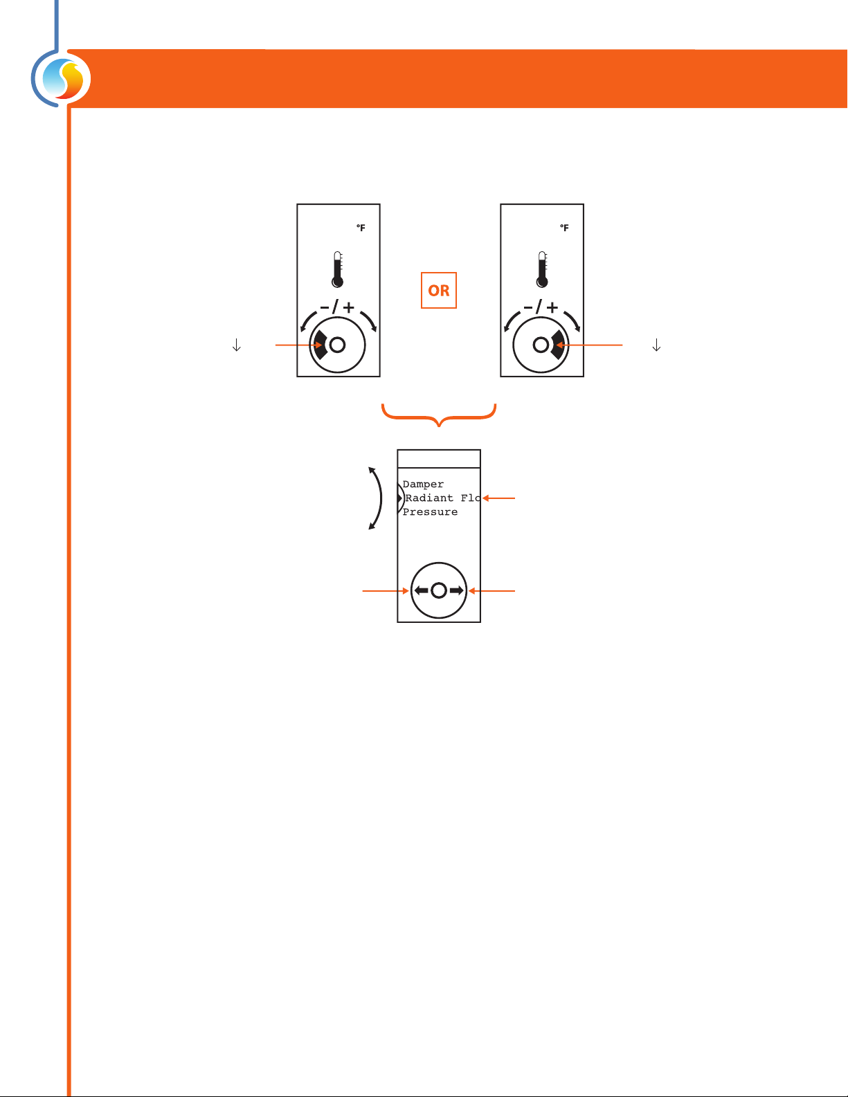
Navigating Menus......................................................................................................................................................... 10
Menu Maps......................................................................................................................................................................11
Visualisation and Options Menu Map.......................................................................................................................................................11
Conguration Menu Map ..............................................................................................................................................................................11
Temperature Menu Map ................................................................................................................................................................................12
Outputs Menu Map..........................................................................................................................................................................................12
Radiant Floor Menu Map ...............................................................................................................................................................................13
Network Menu Map.........................................................................................................................................................................................13
Visualisation Screen.........................................................................................................................................................................................14
Menu Guide........................................................................................................................................................................................................15
Technical Specications ................................................................................................................................................................................ 23
Compliance .................................................................................................................................................................... 24
FCC User Information ..................................................................................................................................................................................... 24
Industry Canada .............................................................................................................................................................................................. 24
Overall Dimensions....................................................................................................................................................... 25

3
REV. 7.3.0 / PL-HRDW-T1100-F-EN
Table of Figures
Figure 1 - Opening Tab............................................................................................................................................................................................5
Figure 2 - Terminal Block Pinout..........................................................................................................................................................................5
Figure 3 - Power Source ..........................................................................................................................................................................................6
Figure 4 - Network Connection............................................................................................................................................................................6
Figure 5 - Network resistor Jumpers ..................................................................................................................................................................6
Figure 6 - Auxiliary Input ........................................................................................................................................................................................6
Figure 7 - Output Specications ..........................................................................................................................................................................7
Figure 8 - Typical Wiring of Digital Output ......................................................................................................................................................7
Figure 9 - Typical Wiring of Analog Output .....................................................................................................................................................7
Figure 10 - Touch Pad Controls.............................................................................................................................................................................8
Figure 11 - Touch Pad Feedback ..........................................................................................................................................................................8
Figure 12 - Touch Pad Hint .....................................................................................................................................................................................8
Figure 13 - T1100 Size Diagram.......................................................................................................................................................................... 25

4
REV. 7.3.0 / PL-HRDW-T1100-F-EN
Description
The T1100 digital thermostats are networkable, microprocessor-based thermostats designed for zoning applications.
Proportional and integral (PI) control loops, working in conjunction with fully customizable outputs (1 analog / 1 digital)
deliver accurate yet exible control strategies. An auxiliary analog input is available for zone temperature averaging or
as a radiant oor slab temperature input. Conguration, performed via a capacitive circular touch pad, is made easy
through an intuitive menu system displayed on a backlit graphic LCD screen.
Part Number Selection
General Information
PL-T1100-WGL
Casing Color:
W = White
B = Black
Label Color
GL = Grey Label
WL = White Label

5
REV. 7.3.0 / PL-HRDW-T1100-F-EN
1. Open casing to remove back cover by pushing on the tab located underneath the thermostat.
(Figure 1)
2. Pull wire(s) through central hole of back cover.
3. Screw in the back cover to the wall.
4. Connect wires:
•Pull out the screw terminal blocks.
•Remove 1 cm insulation from the end of each wire.
•Connect the wires to the terminal blocks: see Figure 2 for pin identication. Typical wiring examples
can be found below.
•Reinstall terminal blocks.
5. Reconnect top cover
Installation
Figure 2 - Terminal Block Pinout
IMPORTANT: Do not install the thermostat under the following conditions:
•Any location exposed to direct sunlight
•On an outside wall
•Near an air discharge grill
•In a location where vertical air circulation is restricted
•Near a dimmer switch
Figure 1 - Opening Tab
6
REV. 7.3.0 / PL-HRDW-T1100-F-EN
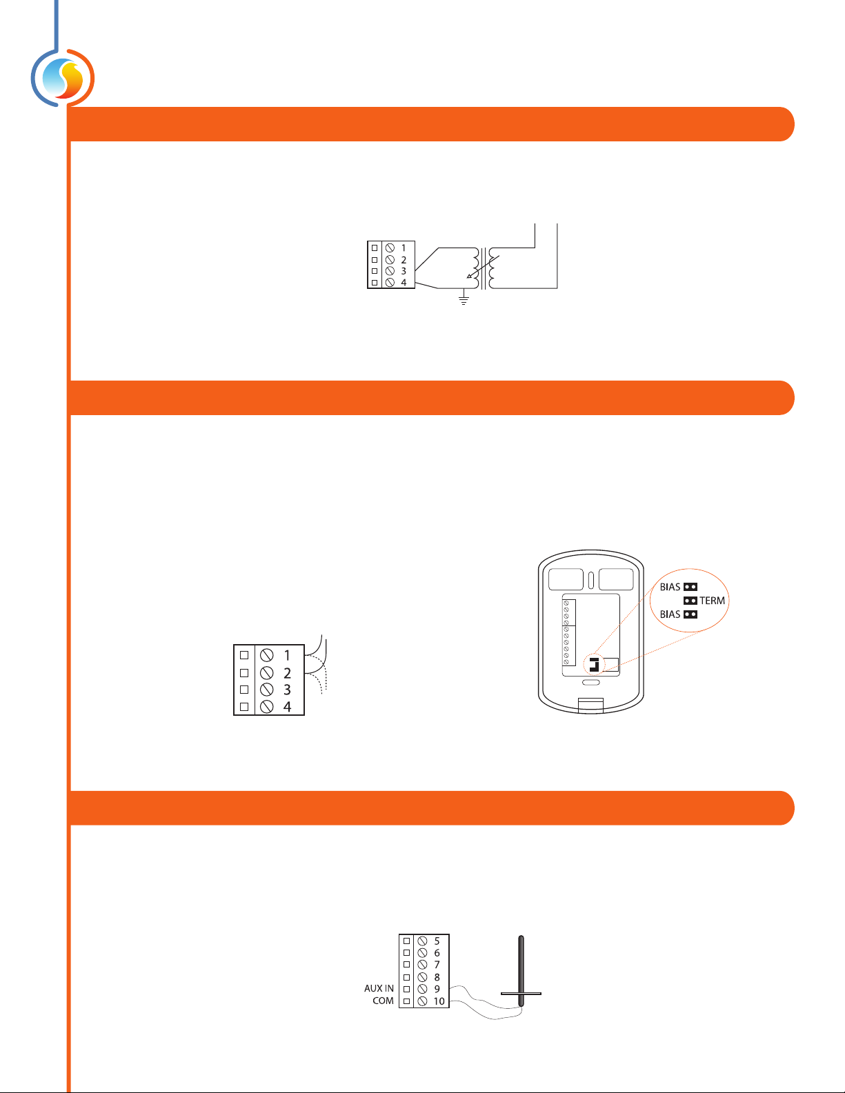
Power Source
Network Setup
The T1100 is powered by a 24 VAC power source connected using the "COM" pin and the "24 VAC" pin. The common for
the power source is shared by the auxiliary analog input and the analog output.
Figure 3 - Power Source
NL
120VAC24VAC
24VAC
COM
The T1100 can work autonomously or networked. When networked, it will communicate in real-time with other Prolon
controllers. The T1100 uses the Modbus RTU protocol over RS485. A unique network address must be assigned to each
device on the network. For the T1100, this can be done through the menu system. The network connections are made us-
ing the “NET A” and “NET B” pins (Figure 4). Bias and terminating resistors can be activated or deactivated using jumpers
on the back of the PCB (Figure 5). Bias and terminating resistors are used to improve signal quality in an RS485 network.
For more information regarding application of network resistors or shielding, see the Prolon Network Guide.
Figure 4 - Network Connection Figure 5 - Network resistor Jumpers
NET A
NET B
RS485
Daisy Chain
Auxiliary Analog Input
The T1100 has an auxiliary analog input which can be used to connect another thermistor. The T1100 can be congured
to use this alternate temperature reading for a variety of functions, including temperature averaging, radiant oor slab
temperature or discharge air control. The alternate thermistor (10KΩ type 3) can be connected to the auxiliary input
using the “AUX IN” and “COM” pins.
Figure 6 - Auxiliary Input

7
REV. 7.3.0 / PL-HRDW-T1100-F-EN
The T1100 series thermostats contain a fully customizable Triac output and a 0-10VDC output to drive components. An
integrated resettable fuse protects both outputs of the T1100 against current surges and short circuits. This protection
will cut the current to the output as soon as an overload condition is detected. The fuse is round and yellow-colored
which, upon a short circuit condition, will heat up and change to orange. When the faulty wiring or circuit is xed, the
fuse will automatically reset and allow current to ow through the output again.
Typical Wiring of the Digital Output
The T1100 opens and closes a triac contact to allow an external source to power the load.
Typical Wiring of the Analog Output
The T1100 provides the control signal to the load, which is powered externally or from the same power source as the
T110 0 .
Outputs Specifications
Figure 8 - Typical Wiring of Digital Output
Figure 7 - Output Specifications
Output Type Heating Cooling
Digital
Passive Sink Triac 10-30 VAC (dry contact)
On-or-O
Pulsed
Max Current: 750 mA
Valve
Relay
Triac
Valve
Relay
Analog
Modulating Output
On-or-O
Max Current: 40mA
Congurable signal:
- 0 to 10 VDC
- 2 to 10 VDC
- 0 to 5 VDC
Modulating Valve
SCR
Relay
Triac
Modulating Valve
Relay
External 24VAC
External Load
DO +
DO -N
Controlled
Load
AO
COM
External
24 VAC
source
N
24v
0-10v
COM
Figure 9 - Typical Wiring of Analog Output
8
REV. 7.3.0 / PL-HRDW-T1100-F-EN
Operation
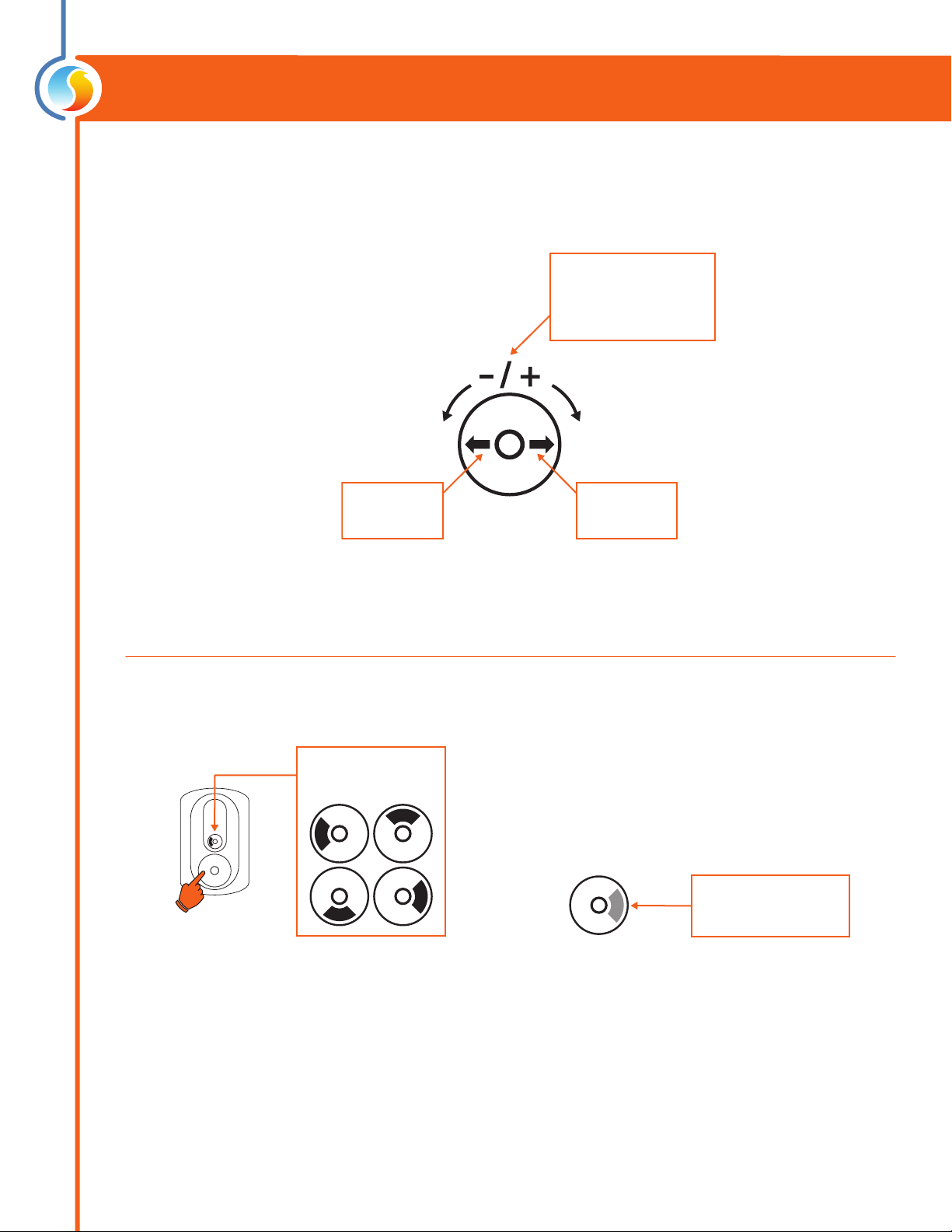
The T1100 is controlled using the circular touch pad on the bottom half of the thermostat. The touch pad uses capacitive
sensing technology to detect nger proximity. There are no moving parts to push or rotate. The T1100 is controlled using
simple scrolling, tapping or holding motions, performed around the circle of the touch pad. The center of the circle is
unused.
Hint Display
At the bottom of the screen, a circle representing the touch pad is displayed, with hints on how to navigate and modify
settings, as well as providing feedback as you manipulate the touch pad. Hints are context-sensitive and will only display
where logical.
Scroll clockwise or
counterclockwise
to adjust or navigate
Tap here to
ENTER
Tap here to
go BACK
Figure 10 - Touch Pad Controls
The black arc
follows your nger
Hold your nger over
highlighted areas to use
special features
Figure 11 - Touch Pad Feedback Figure 12 - Touch Pad Hint
9
REV. 7.3.0 / PL-HRDW-T1100-F-EN
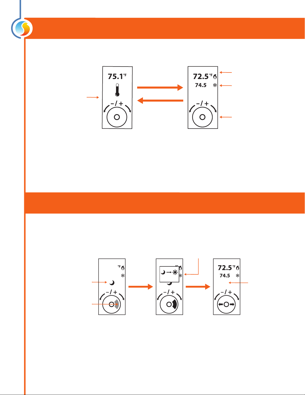
Changing the Setpoint
Scroll or tap
(any direction)
Heat SP
Cool SP
Adjust your setpoint
by scrolling clockwise
or counterckwise
View current zone
temperature
Home Screen Setpoint Screen
Tap anywhere
(or simply wait)
return to
Home Screen
Schedule Override
Counts down
as you hold
(3 sec)
Continue
holding
OVERRIDE ACTIVE
The moon icon indicates
unoccupied mode
HOLD nger
on
highlighted
area
Highlighted area
is blinking
67.5
79.5
67.5
79.5
3
First, go to the Setpoint Screen.
Autres manuels pour T1100
1
Table des matières
Autres manuels Prolon Thermostat


Manuels Thermostat populaires d'autres marques

EWELLY
EWELLY EW-181 Manuel utilisateur

Computherm
Computherm Q20 Manuel utilisateur

Heatmiser
Heatmiser neoStat Manuel utilisateur

Aube Technologies
Aube Technologies TH111GFCI-NP 240 VCA Manuel utilisateur

Mars
Mars HEAT CONTROLLER IR Wireless Thermostat Manuel utilisateur

Saswell
Saswell SAS920XWHB-7-S-RF Mode d’emploi


