Santerno SINUS MV Manuel utilisateur

Q<Q<dQ=dQ<'
]]]
santerno.
IUS
MV DRIVE USER MANUAL
SINUS MV
ELETTRONICA SANTERNO SPA

About This User Manual
This book is only used for SINUS MV series standard Medium Voltage Variable Frequency Drive of Santerno
S.P.A
Technical Support
If you encounter any problem about SINUS MV series Medium Voltage Variable Frequency Drive, please
contact with Santerno S.P.A technical service.
ELETTRONICA SANTERNO SPA
Address: Via della Concia 7 – 40023 Castel Guelfo (BO) Italy
Tel. +39 0542 489711
Fax +39 0542 489722
E-mail: info@santerno.com
Technical support: +39 0542 489990
More detailed information of products please visit our
website: www.santerno.com.
Santerno reserves all rights to this manual, also in the event of patent issue or registration of any other industrial
property protection right. Misuse, in particular duplication and forwarding to third parties, is not permitted.
This manual has been checked with due care and attention. However, should the user find any errors, these
should be reported to Santerno.
Entries in this manual may differ from the actual product, please refer to user’s manual within the production.
Santerno reserves rights to improve products and explain of this manual.
Santerno S.P.A All Rights Reserved.

CATALOGUE
INDEX
Chapter 1 Safety Issues....................................................................................................01
1.1 Introduction. ................................................................................................................................................01
1.2 Notations Defined in this Manual................................................................................................................01
1.3 Advice. ........................................................................................................................................................01
1.4 Safety Measures. ........................................................................................................................................02
Chapter 2 Introduction of SINUS MV Standard MV VFD....................................................03
2.1 Features. .....................................................................................................................................................03
2.2 Technical Parameters. .................................................................................................................................07
2.3 Model and Selection notation......................................................................................................................08
2.4 Application Industries and Fields.................................................................................................................08
2.5 Execute Standards and Norms....................................................................................................................10
Chapter3 Introduction of SINUS MV Theory and Hardware. ...............................................11
3.1 Theory. ..........................................................................................................................................................11
3.1.1 Main Circuit. .......................................................................................................................................................12
3.1.2 Power Cell. .........................................................................................................................................................13
3.1.3 Control System. ..................................................................................................................................................16
3.2 Hardware. ............................................................................................................................................................................1 8
3.2.1 Transformer Cabinet. ..........................................................................................................................................18
3.2.2 Control/ Power Cell Cabinet. ...............................................................................................................................2 1
3.2.3 Power Cell. .........................................................................................................................................................23
3.2.4 HMI. ....................................................................................................................................................................24
3.2.5 Cabinet Door Buttons. ........................................................................................................................................24
3.2.6 Precharge Box. ..................................................................................................................................................24
3.2.7 Switchgears (optional). ......................................................................................................................................25
3.2.8 Remote Control Box. .........................................................................................................................................27
3.2.9 Optional Components. .......................................................................................................................................27
4.1 Cables Selection. ...............................................................................................................................................................28
4.1.1 Power Cable Selection. ........................................................................................................................................28
Chapter 4 Wiring & Terminal Definition................................................................................28

4.1.2 Selection of Control, Signal and Communication Cables................................................................................29
4.2 Primary Wiring.................................................................................................................................................29
4.3 Secondary Circuit Wiring..................................................................................................................................31
4.3.1 Terminal Row Above Interface Board..........................................................................................................31
4.3.2 Terminal Row Below Interface Board..........................................................................................................34
Chapter 5 HMI.......................................................................................................................38
5.1 Touch Screen Interface....................................................................................................................................38
5.2 Touch Screen Display Instructions...................................................................................................................38
5.2.1 Monitoring Interface.................................................................................................................................39
5.2.2 Trend Curve............................................................................................................................................36
5.2.3 Function Parameter and System Parameter................................................................................................42
5.2.4 Restore to Default....................................................................................................................................44
5.2.5 Parameter Download and Upload..............................................................................................................44
5.2.6 Fault Record...........................................................................................................................................45
5.2.7 Other Settings.........................................................................................................................................46
5.2.8 Power Cell Status....................................................................................................................................50
5.3 Important Parameter Description.....................................................................................................................52
5.3.1 Run Mode...............................................................................................................................................52
5.3.2 Stop Mode..............................................................................................................................................52
5.3.3 Control Mode..........................................................................................................................................52
5.3.4 Set Mode................................................................................................................................................52
5.3.5 Start Mode..............................................................................................................................................53
5.3.6 Reverse Rotation Running........................................................................................................................53
5.3.7 Motor Rated Frequency and Voltage..........................................................................................................54
5.3.8 Start Frequency and Minimum Frequency...................................................................................................55
5.3.9 Acceleration & Deceleration Time...............................................................................................................55
5.3.10 Cell Bypass...........................................................................................................................................56
5.3.11 Skip Frequency......................................................................................................................................56
5.4 Appendix.........................................................................................................................................................57
Chapter 6 Function Application..............................................................................................68
6.1 The combination of control mode and set mode..............................................................................................69
6.2 Closed Loop Operation................................................................................................ ...................................69
6.3 Synchronous Transfer Switch...........................................................................................................................70
6.4 Rotating Speed Start........................................................................................................................................71
6.5 MV Loss Solution..............................................................................................................................................71
6.6 Instantaneous Power Stop Function.................................................................................................................73
6.7 Torque Lifting....................................................................................................................................................73
6.8 System Bypass Function (recommended)........................................................................................................74
6.9 Master slave control.........................................................................................................................................74

6.10 Low Frequency Oscillation Restrain................................................................................................................75
6.11 Motor overload protection Function.................................................................................................................75
6.12 VFD Speed Loss Prevention Function............................................................................................................76
6.13 Automatic Adjustment Output Voltage (AVR)...................................................................................................77
6.14 Power Cell Bypass and Neutral Point Drift......................................................................................................77
Chapter 7 Transportation, Storage and Installation..................................................................79
7.1 Requirements of Transportation and Storage...................................................................................................79
7.2 Acceptance Inspection......................................................................................................................................79
7.3 Handling............................................................................................................................................................80
7.4 Installation.........................................................................................................................................................81
Chapter 8 Troubleshooting and Maintenance...........................................................................84
8.1 Light Fault Items and Alarm..............................................................................................................................84
8.2 Heavy Fault Items and Alarm............................................................................................................................84
8.3 Normal Problems processing............................................................................................................................85
8.3.1 VFD trip analysis......................................................................................................................................85
8.3.2 VFD normal faults and solutions.................................................................................................................86
8.4 Power Cell Replacement...................................................................................................................................91
8.5 Maintenance..........................................................................................................................................................91
8.5.1 Routine maintenance and inspection..........................................................................................................91
8.5.2 Regular maintenance...............................................................................................................................92
8.5.3 Spare cell maintenance............................................................................................................................92
Appendix A:Emperature Controller of Dry-type Transformer Setting Instruction...........93
Appendix B:MODBUS Communications Protocol...................................................................99

Thanks for using SINUS MV Standard MV VFD manufactured by Santerno!
SINUS MV Standard MV VFD is a kind of MV electrical equipment, personal safety has been fully considered during
the design process. But it is as dangerous as other MV devices. There exists potentially lethal voltage in the
cabinets, and many other internal high power electric elements are all thermally hot to touch, improper operation
will cause personal injury, equipment damage and property loss.
To avoid personal injury and property losses, before starting work on the SINUS MV Standard MV VFD, standard
safety regulations must be read and followed strictly.
Beginning any installation, commission, starting-up and maintenance work under the instructions in this manual,
the SINUS MV Standard MV VFD is safe.
The safety notations dened in this manual are listed as following. The meanings of these notations keep the
same throughout the document:
We will give technical training about installation, commission, operation and maintenance to the related
personnel, and guarantee that everyone understands the safety instructions in this manual deeply. Besides the
safety instructions presented in this manual, the standard safety regulations of electric power industry must be
abided by.
Santerno will not be responsible for the personal injury or property losses caused by the ignoring of safety
instructions.
01
Safety Issues
Chapter 1
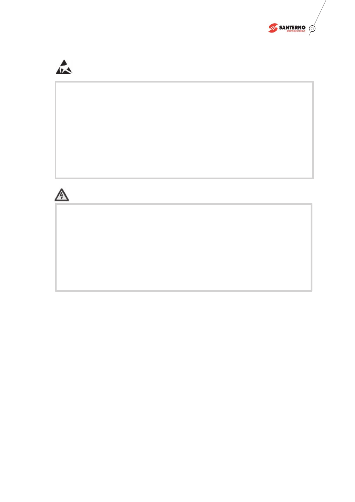
Static electricity!—Static electricity protection to avoid damage to electrical components
and equipment.
Caution!—Warnings that notice the operation to prevent signicant damage to the VFD or to
cause personal injury or death to the related personnel.
Comment:—Key information to help study Santerno products.
1.1 Introduction
1.2 Notations Dened in this Manual
1.3 Advice
Danger!—Operations without following instructions can cause personal injury or death.

02
SANTERNO USER MANUAL
The designs and safety instruments of SINUS MV Standard medium voltage VFD is safe with proper installation,
commission, operation and maintenance. To avoid the man-made accidents, the following safety regulations must
be abided by:
1.4 Safety Measures
Caution!
Only qualified individuals/personnel shall install, operate, troubleshoot, and maintain the drive. A
qualied individual is one who passes the strict training and is familiar with the construction and
operation of the equipment and the regulations of electric power industry.
Always working with another person present when testing operating and maintaining of the drive.
Always wearing insulated shoes when commissioning, operating and maintaining.
Preparing MV test pencil, grounding wire, protective rail and caution board before examining or
maintaining the SINUS MV Standard medium voltage VFD.
When connecting the external wires, the related regulations and standards of electric power industry
should be abided by.
To avoid personal injury and property losses, before any operation the safety regulations in this
manual must be read carefully.
SINUS MV Standard MV VFD must be placed at proper environment, and be at a maintainable state.
Only professional individuals are allowed to install, connect or set the parameters of the drive. If
modify parameters, must contact with Santerno to conrm.
In case of VFD failure causing an accident or damage, the user and its designer must consider the
complete safety solutions during the selection of VFD and corollary equipment.
Only restart the drive and switch on the main input power to the equipment after inspection and
maintenance procedures when VFD trip.
There are heating elements in VFD cabinet. Before maintenance, never touch anything within the
cabinets until verify it is neither thermally hot nor electrically alive after turning off the VFD.
●
●
●
●
●
●
●
●
●
●
●

03
Caution!
●
●
●
●
●
●
Static electricity!
Electric devices are sensitive to static electricity. When installing, maintaining, closing or touching
with the elements in VFD cabinet, the related personnel must put on electrostatic-proof bracelet.
Nonprofessionals are not allowed to touch the electric elements.
During the transportation and storage of the electric elements or circuit boards, electrostatic-proof
package must be used.
When installing or touching the circuit boards, hold the rim of the circuit board, avoid touching the
electric elements in the circuit board.
Hazardous voltage may still exist within the cabinets even when the supply power is shut off.
Isolate the VFD reliably (contactor cannot be used as isolator), the inputs and outputs of VFD are
connected with ground, do not touch the components of the main power circuit until conrming
that the charging light is off.
Always work with one hand, wear insulated shoes and gloves.
Never run the drive with cabinet doors open, except for the secondary cabinet.

04
SANTERNO USER MANUAL
Introduction of SINUS MV Standard MV VFD Chapter 2
2.1 Features
SINUS MV Standard MV VFD is manufactured by Santerno. It is equipment for use with medium voltage (synchronous
or asynchronous) AC motor speed adjusting and driving. It has the following functions and features:
●SVPWM control technology has advantages of high control accuracy, fast response, and more than
98% VFD efciency;
● Modular design of power cell, convenient to maintain;
● Wide input voltage range meets the demand of grid;
●Power cells connecting in series topology and wave stacking method, well developed technique and
reliable devices;
●Output voltage has AVR (automatic voltage regulating) voltage stabilizing function of to prevent
damage to motor insulation from over-voltage and reduce the motor wear and tear;
● Torque boost function, raise output voltage & output torque during low frequency running;
● Rotating speed (ying-start) start function, realize the motor restart during rotating, meet the
continuous production requirement;
●Instantaneous power outage function, inverse charging to ensure normal running when the network
loss power in a very short time;
● Auto-start on MV trip, suitable for working conditions like dual power switch and grip voltage loss;
●Synchronous transfer switch function (optional), realize “no disturb” motor switch between grid and
VFD, reduce the impact to equipment and grid;
● Power cell by-pass function (optional), automatically bypass the failure cell without inuence the VFD
running;
●English HMI easy for operation, (eight languages are optional).
●Synchronous motor, synchronous/asynchronous start
●Master-slave function to make multiple VFD control
●Compact design and proper arrangement( possible to do special design according to customer
requirements)
Besides above advantages, SINUS MV Standard MV VFD has the following functions and features:
●Motor over-load protection
●Over-current protection
●Input Phase loss protection

05
●Over-voltage protection
●Over-heat protection
●Current limit function
●Control power fault protection
●Two-path redundancy of control power
● Power cell communicate with controller through optic ber, completely electric isolated
● System running in closed-loop, able to use the expected value of eld controlled volume (such as pressure,
temperature etc.) set by the users to adjust the motor rotating speed automatically. For instance: constant
pressure water supply system can realize pressure constant control
●Multiple communication methods with host computer, isolated RS485 interface, standard MODBUS RTU
communication protocol, PROFIBUS DP (optional), industrial Ethernet communication protocol (optional)
●Accurate fault records, able to search information and locate the faults
●Cabinet door opening alarm function
The power supply input and output of SINUS MV Standard MV VFD meet the most stringent IEEE STD 519-1992
and GB/T14549-1993, no need for a separate input lter, the cost for harmonic elimination is saved for customers.
Because of the high power factor of the system, the compensation device for power factor is not needed, thus the
reactive input and the input capacity are reduced, and the cost for capacity increasing of power grid is minimized.
Using an isolated transformer, the input of SINUS MV Standard MV VFD could be isolated to grid. By phase shifting
of the secondary winding and multi-pulse diode rectier, isolated power can be acquired and supplied for power
cells.(30/36 pulses for 6kV, 54 pulses for 10kV(By using the technique of multi-pulse rectifier, the harmonic
current caused by individual power cell could be eliminated greatly.
Figure 2.1 30 pulse input waveform (CH1 voltage, CH3 current)
Table des matières
Autres manuels Santerno Entraînement CC
Manuels Entraînement CC populaires d'autres marques

Vincent Associates
Vincent Associates UNIBLITZ ED12DSS Manuel utilisateur

EKSMA OPTICS
EKSMA OPTICS DQ-100-4 Manuel de la liste des pièces

Chamberlain Garog
Chamberlain Garog D Series Manuel utilisateur

Parker
Parker PDS Series Manuel utilisateur

Festo
Festo DGC G Series Guide de configuration

Binks
Binks QS-5012-1-CE Manuel utilisateur