Safe Fleet inView 360 Core Manuel utilisateur

MAY 2021 | Part #: 700-1262 R1.0
© Safe Fleet | All rights reserved
Installation Guide
inView 360 Core
Around Vehicle Monitoring System

MAY 2021 | Part #: 700-1262 R1.0
© Safe Fleet | All rights reserved p. 2
inView 360 Core Installation Guide
Introduction
The InView 360 Core is a high-denition multi-camera system that provides drivers with a top-down “bird’s eye” 360° view of
the area around their vehicles. Large vehicles, due to their size and shape, often have areas which drivers cannot see unaid-
ed. By providing drivers with a full 360° view of the area around their vehicles, the InView 360 Core helps to eliminate these
vehicle “blind spots”, contributing to the reduction of collisions with surrounding pedestrians and vehicles.
How Does the InView 360 Core Work?
High-denition cameras are placed high up on the front, rear, left, and right sides of the vehicle. Videos from these four
cameras are sent to the on-board computer, which, with the help of proprietary software, stitches/combines these video
feeds to create the 360° view of the area around their vehicles.
Cameras
Camera FoV
Cameras and Camera Fields of View (uncombined)
Combined 360° Video
Camera FoV
Cameras
NOTE: Installation Locations
Vehicle makes, models and sizes vary. Therefore, this document does not specify exact locations for the kit’s
components. Instead, this document describes the best locations for installing components for optimal operation and
ideal placement of cameras for optimum elds of view.
Cameras and Camera Fields of View (combined)

MAY 2021 | Part #: 700-1262 R1.0
© Safe Fleet | All rights reserved p. 3
inView 360 Core Installation Guide
Installation Process
There are multiple steps to be performed by different team members:
1. Install the inView 360 HD system
2. Calibrate the inView 360 HD system (See the inView 360 HD System Calibration Guide)
3. Verify that the inView 360 HD system was correctly installed and calibrated (See the inView 360 HD Verication and
Setup Guide)
Each step requires a specic skill set from the person who performs it.
NOTE: Installation Process
This document assumes that the installer is familiar with installing hardware in a vehicle. Therefore, this document
does not go into detail to describe how to mount the ECU and cameras, and how to route the kit cables.
Mounting the ECU
The ECU should be mounted in a location underneath the dashboard or somewhere within the vehicle where it is protected
from water, dirt, and physical contact, and it should have ample ventilation.
Accessibility
When installing the ECU, ensure that the IR Extension and USB cables are easily accessible. The USB cable will be used for
future rmware upgrades. The IR Extension must be placed so that no obstructions interfere with receiving a signal from the
IR remote.
Routing Cables and Connectors
After you have selected an optimal location for the ECU, and mounted it, you can begin routing the power, signal, radar/
proximity sensors and buzzer cables, as well as the push button.
Kit List
ECU Green Push Button
Flasher harness Cameras and cables (x4 each)
Camera connections harness IR extension
Power harness IR remote
Interface Harness, which contains the following: AHD cable, CVBS cable, Radar Cable, Buzzer cable, USB cable, harnesses
for ashes/triggers and for the button

MAY 2021 | Part #: 700-1262 R1.0
© Safe Fleet | All rights reserved p. 4
inView 360 Core Installation Guide
Camera Placement Considerations for Long-Nosed Vehicles
Placing Cameras
It is important to keep vehicle type/shape in mind when considering camera placement. Also, it is important to keep in mind
the physicality of the vehicle when placing cameras. Watch out for mirrors and other vehicle elements that can create a
blind spot in the camera view.
General Camera Placement Considerations
When considering where to mount the cameras, it is important to follow these general guidelines:
• Place the cameras as high and as centered as possible to ensure that there are no immediate obstructions in the
camera’s eld of view.
Examples of Camera Placement on Commercial Vehicles
Examples of Camera Placement on School Buses
Mount the camera at the tip of the hood
on vehicles with “long noses” to get the
maximum eld of view.
You can see more by lowering the front
camera to the tip or nose of the hood.
Positioning the camera here allows
drivers to see more of what’s on the
road in and around the front of the
vehicle, especially pedestrians.
When mounting cameras on vehicles
with long noses, you should consider
that vehicle elements such as the roof
of the cab or the side mirrors might
obstruct the camera’s eld of view.

MAY 2021 | Part #: 700-1262 R1.0
© Safe Fleet | All rights reserved p. 5
inView 360 Core Installation Guide
Camera Placement Considerations for Specially Shaped Vehicles
Vehicles that have special compartments or equipment in the middle, such as re trucks, might require special
consideration for mounting cameras. Because of the accessories and equipment that is usually added to emergency
vehicles, mounting the cameras high up and in the center might not be an option. The added equipment might block a
camera’s eld of view.
This is a situation where you should consider mounting the camera slightly off center.
Vehicle Center
In these illustrations, you can see that the cameras have been mounted slightly off
center to compensate for elements on the vehicle body that could block the camera’s
eld of view.
NOTE: Images are for illustration only
These images are just representations of camera placement. The orange areas do
not accurately portray the actual camera eld of view. Please refer to your camera
specications for a more accurate representation of the cameras’ elds of view.

MAY 2021 | Part #: 700-1262 R1.0
© Safe Fleet | All rights reserved p. 6
inView 360 Core Installation Guide
Putting the Components Together
Connecting to the Power Source
When connecting to the power sources, please ensure the following:
• Red goes to vehicle power
• Yellow goes to vehicle ignition
• Black goes to vehicle ground
TIP! Cutting the Power Lines
It is important that the “extension” power lines are cut to length.
Signals
Triggers
USB
AHD
CVBS
Radar
Speaker
Front Cam
Rear Cam
Right Cam
Left Cam
VCC (Battery)
ACC (Ignition)
Ground
IR Extension
Letter Name
AInterface Harness
B Camera Connections Harness
C Power Harness
A
B
C
Harnesses

MAY 2021 | Part #: 700-1262 R1.0
© Safe Fleet | All rights reserved p. 7
inView 360 Core Installation Guide
Connecting Cameras to the ECU
The cameras are labeled to indicate where they should be mounted on the vehicle - FRONT, RIGHT, LEFT, REAR. When
connecting cameras to the ECU, it is important that you do the following:
• Connect the labeled camera to the correct corresponding camera interface on the ECU harness.
• Connect each camera to an extension cable before connecting it to the ECU.
Follow the diagram below to connect the cameras.
Signals
Triggers
USB
AHD
CVBS
Radar
Speaker
Front Cam
Rear Cam
Right Cam
Left Cam
VCC (Battery)
ACC (Ignition)
Ground
IR Extension
4 x Camera
Extension Cables 4 x Camera Units
C
o
n
n
e
c
t
t
o
C
o
n
n
e
c
t
t
o
NOTE: Using the Correct Cables
It is important that you use the correct button and camera extension cables. They are labeled for your convenience.
NOTE: Choosing the Correct Camera Extension Cable
Camera extension cables are labeled and come in 3 different lengths:
• 8m Front
• 12m Left, Right
• 15m Back
Please ensure that you use the correct cable for the camera.

MAY 2021 | Part #: 700-1262 R1.0
© Safe Fleet | All rights reserved p. 8
inView 360 Core Installation Guide
Connecting Monitors
Connecting an HD Monitor to a Power Source via the Power Harness
Use the AHD connector from the Interface Harness to connect to an HD monitor. You will need a video cable and power
harness, which are sold separately.
Signals
Triggers
USB
AHD
CVBS
Radar
Speaker
Front Cam
Rear Cam
Right Cam
Left Cam
VCC (Battery)
ACC (Ignition)
Ground
IR Extension
Connect the video
cable to the AHD
connector on the
Interface Harness.
Connect the Power
Harness to a power
source. Connect the
Red wire to the Ignition
(ACC) and the Black
wire to the ground.
HD Monitor
MAY 2021 | Part #: 700-1262 R1.0
© Safe Fleet | All rights reserved p. 9
inView 360 Core Installation Guide
Signals
Triggers
USB
AHD
CVBS
Radar
Speaker
Front Cam
Rear Cam
Right Cam
Left Cam
VCC (Battery)
ACC (Ignition)
Ground
IR Extension
CVBS
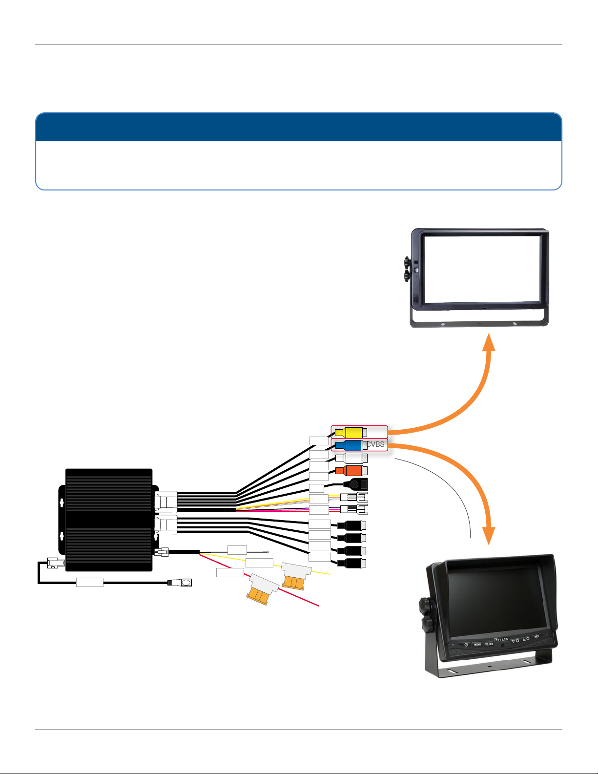
Connecting the ECU to a Standalone (Single) Monitor
It is recommended that you connect the InView 360 Core system to an in-cab monitor. This allows drivers to view the area
around their vehicle.
Standard
monitor
NOTE: Where to nd a monitor
Monitors are sold separately and are not included in the InView 360 Core system kit. You should have received a
monitor in your installation package. If you do not have a monitor to install, please inform the client, or contact Safe
Fleet for assistance.
If you are installing the InView 360 Core as a standalone system (without a Safe Fleet DVR or NVR), then you can simply
connect the monitor directly to the ECU harness’ CVBS cable or to the AHD cable.
AHD
HD monitor
Choose the connection method for the type of monitor that will be used:
• To connect to a standard monitor, use the CVBS connector
• To connect to an HD monitor, use the AHD connector
Both of these setups can be congured so that the video feed to the monitor
cuts off when the vehicle attains a certain speed. Please see the inView 360
for instructions.
4
p
-
t
o
-
R
C
A
c
a
b
l
e
(
0
6
0
-
1
1
9
9
)

MAY 2021 | Part #: 700-1262 R1.0
© Safe Fleet | All rights reserved p. 10
inView 360 Core Installation Guide
Connecting the ECU to a Monitor and a Second Device via the
CVBS Connector
A Y-Splitter can be used to split the CVSB video line to connect to a
second standard resolution monitor.
Signals
Triggers
USB
AHD
CVBS
Radar
Speaker
Front Cam
Rear Cam
Right Cam
Left Cam
VCC (Battery)
ACC (Ignition)
Ground
IR Extension
Primary monitor
(Example monitor
shown)
CVBS
Additional hardware
required for connecting to
a Safe Fleet recorder or
additional monitor
Y-Splitter
Second standard
monitor
4p-to-RCA cable
(060-1199)
4p-to-RCA cable
(060-1199)
Table des matières
Autres manuels Safe Fleet Instrument de mesure


Manuels Instrument de mesure populaires d'autres marques


Endress+Hauser
Endress+Hauser Proline Promag 50 Caractéristiques techniques

Siemens
Siemens SITRANS F Coriolis FCT030 Manuel de la liste des pièces

KLINGER
KLINGER CMF V Series Manuel utilisateur

EXFO
EXFO FTB-2 Manuel d'exploitation et d'entretien

Keysight
Keysight M8290A Manuel utilisateur

ADTEK
ADTEK MW-5 Manuel utilisateur