Rotary Compression Technologies LeROI HG10 Instructions de montage

ISO 9001-2000
Installation – Operations
Maintenance and Service Guide
LeROI Gas Compressors
By Rotary Compression Technologies, Inc.
Rotary Screw Compressor
Models:
HG10
HGF10
HG12
HGF12
HGS17
HGSF17
HG17
HG24
LG30
LGL30
RCT-INST001 Rev 6 -8/08
ECN 48316

ROTARY COMPRESSION TECHNOLOGIES, INC.
THANKS YOU FOR PURCHASING LEROI GAS
COMPRESSORS, MODULES AND PARTS

Table of Contents
Safety Information and Warnings________ _________________1
Protecting Your Compressor Before Service_________________2
Identifying Your Compressor_____________________________3
Understanding Your Compressor_________________________4
The Compressor System______________________________5-6
Oil Flow and Orifice Sizing____________________________7-10
Variable Vi Adjustment______________________________11-13
Versatrol (Capacity Control)__________________________14-15
Oil and Related Items_________________________________16
Installation________________________________________17-18
Installation – Component Location________________________19
Operation and Preventive Maintenance____________________20
Service Procedures - Components_____________________21-29
Rebuild Kits_________________________________________30
Website____________________________________________31
Contact List_________________________________________32
Service Diagnosis____________________________________34
Warranty___________________________________________35

1
LeROI gas compressors are designed with safety in mind. However, there is no substitute
for safe operating procedures. Throughout this manual, there will be additional “Notes”,
“Cautions” and “Warnings” intended to protect the operator and the equipment. These
additions are not all inclusive. Extreme care must be exercised when operating or servicing
this equipment.
The operator and or serviceperson should:
•Be knowledgeable of one’s equipment.
•Develop safe work habits.
•Never operate a unit without guards and shields in place.
•Never operate a unit that is not properly electrically grounded.
•Never service a unit with the pressure in the receiver-oil reservoir unless
following specific operation manual instructions.
•Never service a unit without disconnecting and locking out the electrical
power supply unless following specific operation manual instructions.
•Take all necessary precautions, when adjusting controls, etc., to prevent
electrical shock.
•Take all necessary precautions when working with flammable gases to prevent
fire or explosion.
Safety Information and Warnings
A Careful Operator is the Best Insurance
A
gainst an
Accident

2
THIS COMPRESSOR IS SHIPPED WITHOUT OIL. ALTHOUGH
RESIDUAL OIL FROM THE FACTORY TEST IS SUFFICIENT TO PREVENT
RUST DURING SHIPPING, IT DOES NOT PROVIDE ADEQUATE
PROTECTION FOR STORAGE.
IF THE COMPRESSOR WILL NOT ENTER SERVICE WITHIN ONE WEEK OF BEING
RECEIVED, COMPRESSOR OIL MUST BE ADDED THROUGH THE GAS INLET SO THAT
ITS LEVEL IS AT LEAST AS HIGH AS THE BOTTOM OF THE INLET CAVITY. ALLOW A
FEW MINUTES FOR THE OIL TO FILL INTERNAL CLEARANCES THEN ADD TO BRING
LEVEL BACK UP. REINSTALL THE INLET COVER PLATE AND BOLT IT DOWN
SECURELY. THE DRIVE SHAFT MUST BE ROTATED ½ TURN MONTHLY TO INSURE
THAT ALL MOVING PARTS HAVE AN OIL COATING.
Protecting Your Compressor Before Service

3
LeROI gas compressors have a nameplate that provides valuable information
on your compressor. This information is needed for ordering parts and
conversion kits, as well as for accessing warranty information and
understanding the design of the compressor. Below is a Model Designation
chart to help you identify your
compressor.
Identifying Your Compressor
4
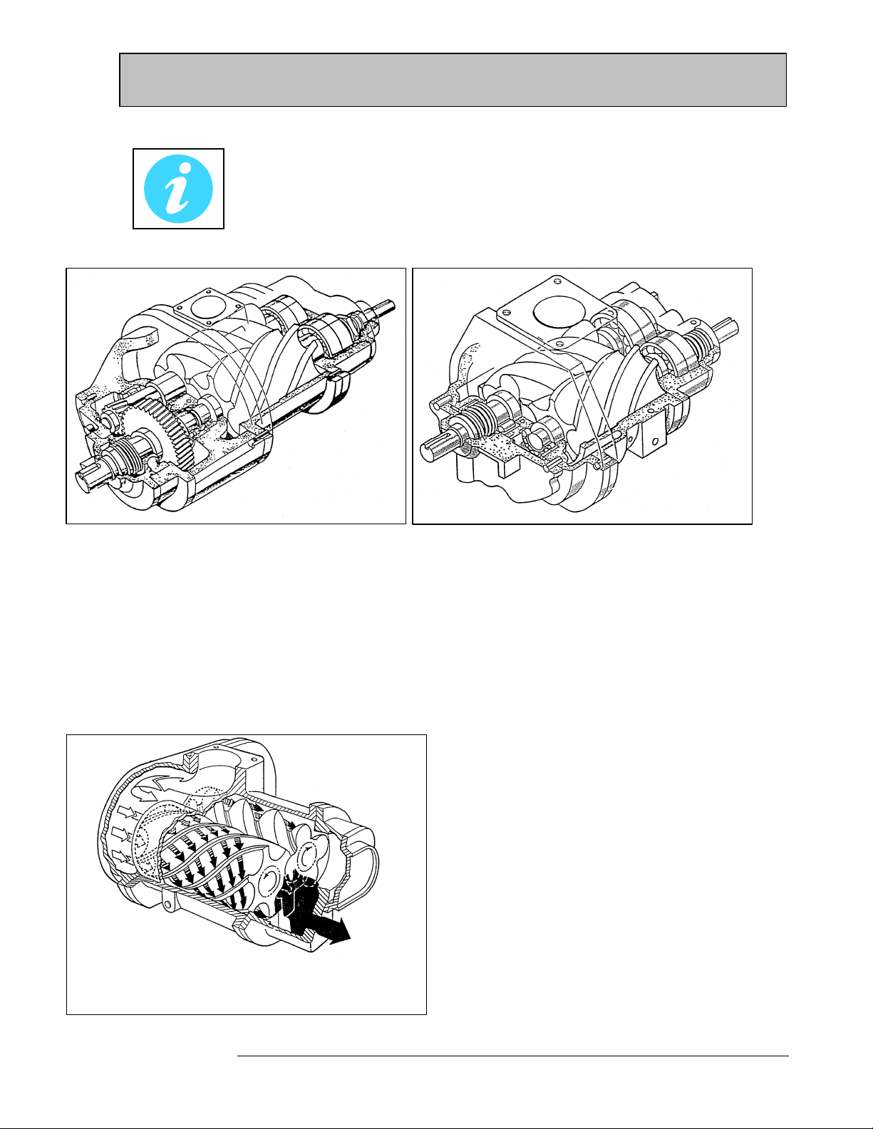
Your compressor is either a LG (Low Pressure) or HG (High Pressure) single stage,
positive displacement, oil-flooded screw compressor. There are two basic general
configurations; geared (Figure 1) and non-geared (Figure 2).
Figure 1 - geared compressor Figure 2 -Typical non-geared compressor
Oil-flooding provides cooling, lubrication and sealing in the compressor. The oil must be cooled using either water
or air in a heat exchanger that is properly sized for all operating conditions.
Geared units (Figure 1) come standard with integral gearing to increase or decrease the speed internally, allowing
for direct connection with standard drivers. The drive (input) shaft is an integral extension of the male rotor.
Compressors with gears use an independent input shaft, commonly referred to as a jackshaft, mounted on roller
and/or special deep groove ball bearings. The gear mounted on the jackshaft drives the gear mounted on the male
rotor and the male rotor meshes with and drives the female rotor.
Figure 3 shows the direction of the rotor rotation and
the gas/oil flow through the compressor. Note that
this flow is between the rotors and the inside diameter
(bore of the cylinder).
The uncompressed gas enters the compressor at the
inlet flange, passes into the front bearing retainer, and
enters the cylinder bore at the front (inlet) end. (Figure
3). As the gas passes a predetermined inlet cut-off
point in the cylinder, compression takes place due to
decreasing rotor to cylinder volume as the rotors turn.
Gas at the desired pressure is discharged at the rear
(discharge) end. Oil is injected into the compressor at
specific locations for cooling.
Understanding Your Compressor
Figure 3 - Oil/Gas Flow-Typical

5
The LeROI gas compressor is one part of the compressor system. The compressor combined with the
driver forms the heart of the system. However, the other vital elements are essential to ensure the heart
of your system continues to operate.
Suction Scrubber (with filtration, if necessary)
This is required to prevent the carry over of liquids into the compressor. Filtration is often necessary, especially in vacuum
installations, to prevent debris (e.g. iron sulfides) from getting into the compressor.
Gas/Oil Separator
The gas/oil separator is a key component of the compressor system. The separator should be designed to handle the
maximum capacity at the lowest discharge pressure and the highest discharge temperature. It is important that the vessel and
coalescing filter are sized properly to insure optimum gas and oil separation. The separator also acts as the oil reservoir (oil
sump), with the oil collecting in the bottom.
Oil Cooler
The oil cooler is an air-cooled or water-cooled heat exchanger that is sized to suit the size (capacity) of the compressor being
cooled. The cooler should be designed to handle the worst operating condition, which is usually based on the lowest suction
pressure and the highest discharge pressure. However, the oil flow plays a critical role in determining the heat rejection of the
oil cooler.
Minimum Pressure Valve
The minimum pressure valve is recommended to maintain a minimum pressure in the gas/oil seperator. It is especially
important to use this device when the possibility exists that the system pressure may not be sufficient to maintain pressure in
the seperator to achieve adequate gas/oil seperation.
Thermal By-Pass Valve
The injection temperature of the oil used to cool, seal, and lubricate the compressor is controlled by the thermal by-pass
valve. As the name implies, this valve allows part or all of the oil flow to by-pass the oil cooler, depending on the temperature
of the oil leaving the compressor. This valve can be controlled thermostatically or with more sophisticated temperature
control valve where more precise control of oil temperature is required.
The Compressor System

6
Oil Filter
It is extremely important that the oil injected into the compressor be as clean as possible. The oil filter should be generously
sized to handle full oil flow, and should have a filter element that will remove particles down to 10 micron. If the compressor
is in an application where continuous operation is important or where the filter will get dirty in a short period of time, it is
recommended that a dual filter arrangement be used.
Instrumentation and Controls
The compressor has operating limitations that must be monitored. Protective devices are required to the protect the
compressor from experiencing a catastrophic failure. These include, but are not limited to high temperature and pressure, as
well as liquid level switches in the suction scrubber where there is a potential for large amounts of liquid in the gas stream.
Figure 4 – Typical Basic Piping Diagram
The Compressor System (Continued)

7
As mentioned previously in this manual, rotary screw compressors require oil lubrication of
the bearings, cylinder and rotors. Bearing lubrication is necessary for long life. Cylinder and
rotor lubrication does three things:
1. Reduces friction between the rotors
2. Provides a seal between the cylinder and rotors to reduce gas slippage.
3. Cools the gas.
In certain applications the pressure differential (discharge-suction) is such that an oil pump is not required.
However, if the application has a lower pressure differential than an oil pump will be required. It is
important for the application to be reviewed especially if the unit will be moved from one site to another
resulting in different conditions.
LeROI gas compressors have an oil injection manifold that distributes oil supplied by the pump or pressure
differential. The orifice creates a restriction. A smaller orifice results in a greater restriction, which forces
more oil to the bearing and less oil to the rotors. The goal is to create a proper balance in the compressor
for reliable operation.
Oil Flow and Orifice Sizing
Figure 5 –
T
ypical Oil Flow Figure
6
– Orifice Installatio
n
Ce manuel convient aux modèles suivants
9
Table des matières
Manuels Compresseur d'air populaires d'autres marques


Campbell Hausfeld
Campbell Hausfeld RP3300 Guide de démarrage rapide

Ingersoll-Rand
Ingersoll-Rand UP6 20 HP Manuel utilisateur

Hitachi
Hitachi EC99S Manuel de l'opérateur

Parkside
Parkside PKO 270 A1 Manuel utilisateur

Sullair
Sullair 185 Manuel utilisateur

Clas Ohlson
Clas Ohlson QIE-ZTH-15 Manuel utilisateur


