Ronix RWS-XE5DIP3610M-IR Manuel utilisateur

5Mega pixel Motorized Zoom
Network Bullet Camera
Before installing and using this product,
please read the instruction fully and keep it handy for later use.
5MP
Preliminary
Operating Instruction

CAUTION: TO REDUCE THE RISK OF ELECTRIC SHOCK,
DO NOT REMOVE COVER (OR BACK).
NO USER SERVICEABLE PARTS INSIDE.
REFER SERVICING TO QUALIFIED SERVICE PERSONNEL.
To prevent fire or shock hazard, do not expose the unit to rain or moisture.
To prevent electric shocks and risk of fire hazards, do NOT use other than
specific power source.
Warning :
This equipment has been tested and found to comply with the limits for a Class
A digital device, pursuant to part 15 of the FCC Rules. These limits are designed
to provide reasonable protection against harmful interference when the equipment
is operated in a commercial environment. This equipment generates, uses, and
can radiate radio frequency energy and, if not installed and used in accordance with
the instruction manual, may cause harmful interference to radio communications.
Operation of this equipment in a residential area is likely to cause harmful
interference in which case the user will be required to correct the interference at
his own expense.
Caution :
Any changes or modifications in construction of this device which are not expressly
approved by the party responsible for compliance could void the user's authority
to operate the equipment.
Mains power quality should be that of a typical commercial environment. If the user
of the model requires continued operation during power mains interruptions, it is
recommended that the model be powered from an uninterruptible power supply
(UPS) or a battery.
The symbol is intended to alert the user to the presence of important
operating and maintenance(servicing) instructions in the literature
accompanying the unit.
The symbol is intended to alert the user to the presence of uninsulated
"dangerous voltage" within the product's enclosure that may be of
sufficient magnitude to constitute a risk of electric shock to persons.
Safety Precaution
03
MEGA-PIXEL NETWORK CAMERA

Safety Precaution
04
MEGA-PIXEL NETWORK CAMERA
NOTICE
• The image used in this instruction manual are processed to help comprehension
and may differ from actual video of the camera.
• Avoid installing areas where has shock or vibration which results in the problems.
• Pay attention to safety when laying the connection cable and observe that the cable
is not subjected to heavy loads, kinks or damage and no moisture can get in.
• Never open the device such as boards or lens.
The warranty becomes void if repairs are undertaken by unauthorized persons.
• Maintenance and repair have to be carried out only by authorized service centers.
• Use only a mild detergent to clean the housing body only but never for the clear
bubble dome.
• The camera should never be operated beyond the technical specifications.
This can lead to destruction.
• The camera should never be operated in water.

Contents
05
MEGA-PIXEL NETWORK CAMERA
Safety Precaution
p.03~04
Contents
p.05
Features
p.06
Composition
p.07
Dimensions
p.07
Part Names
p.08
Installation Instructions
p.09~11
Operating Instructions
p.12~20
Troubleshooting
p.21~22
Specifications
p.23~24

Features
06
MEGA-PIXEL NETWORK CAMERA
• 5.04Mega Pixel, NETWORK CAMERA, 2592x1944(15p/12.5p)
• ONVIF Conformance
• Zero configuration
• Cross Web Browsing (IE, Edge, Safari, Firefox, Chrome)
• Adaptive web resizing depending on layout & resolution of
display device by RESPONSIVE WEB
• Increased usability for all PC, tablet and mobile
• Simultaneously H.264 & MJPEG (Triple streaming)
• 2 Way Audio & Alarm input/output
• ONVIF Event Mapping
• HTML5 playback
• Slot for Micro SD memory card
• f=3.6~10mm F1.5, 6Mega pixel Motorized Zoom lens
• Dual Filter Switcher
• SNAP Focus by Motorized Zoom lens
• Motorized Zoom & Focus Adjustment
• D-WDR (Digital Wide Dynamic Range)
• Improved noise figure with the enhanced 3DNR
• Motion Detection, Privacy Mask, Tamper, Defog, BLC/HLC, Hue,
D-Zoom(~16x), Mirror/Flip, LDC(Lens Distortion Correction), Contrast,
Brightness, Saturation, Sharpness, Auto-Flickerless, VerticalView
• Circuit protection against faulty connection in power polarity
• Isolated power supply against ground loop problem
• PoE(IEEE Std. 802.3af) & AC24V/DC12V
• Built-in 4pcs High power LED
• Built-in LED Auto/Off Switch
• Built-in Fan & Optimized Cooling system
• Dual Window
• One touch 3-Axis locking bracket
• IP68 Protection
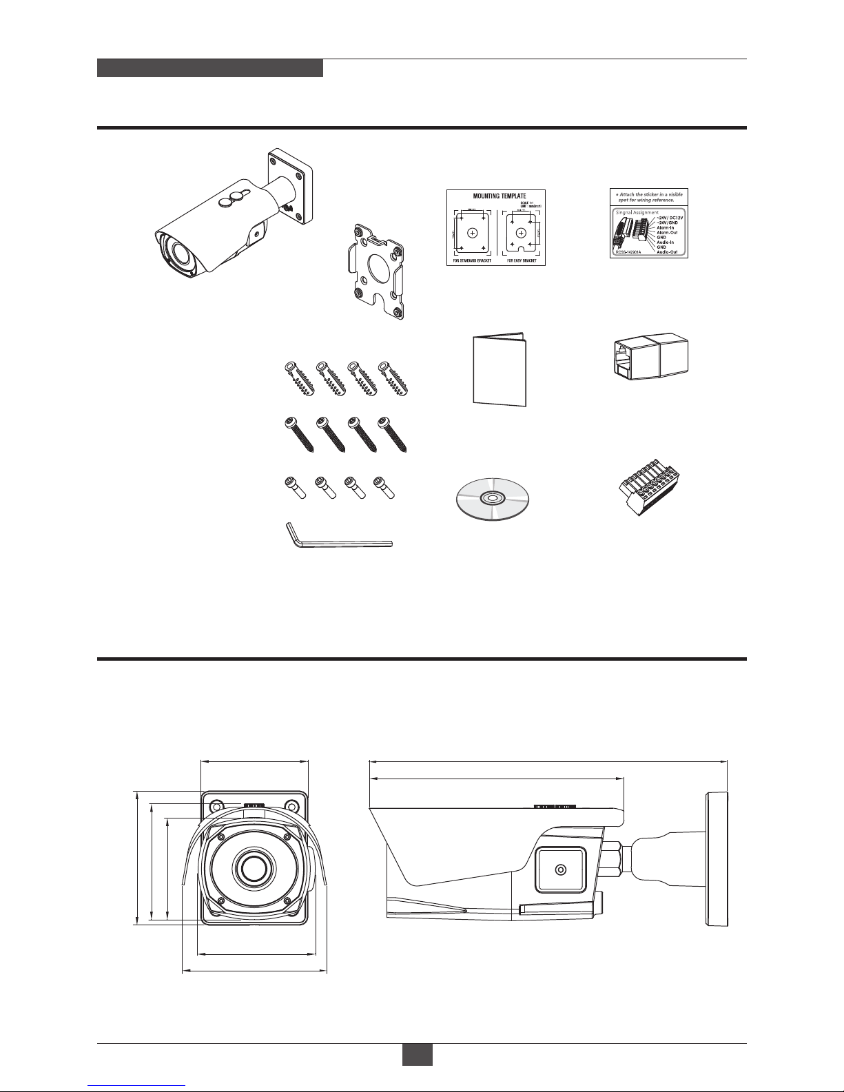
Composition
07
Dimensions
MEGA-PIXEL NETWORK CAMERA
(unit : mm)
Installation CD
Coupler for
RJ45 Cable (1pc)
Wiring Connector
(1pc)
Cable Signal
Sticker
Torque Wrench:
3mm (1pc)
Mounting Template
Operating Instruction
Camera
Easy
Bracket
267
108
87.30
100
86.40
75.90
80
190
Mounting Screw:
4 x 30mm (4pcs)
Plastic Anchor:
6 x 30mm (4pcs)
Assembly Screw:
4 x 15mm (4pcs)
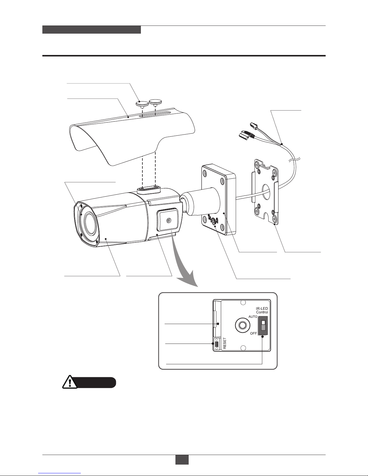
Part Names
08
MEGA-PIXEL NETWORK CAMERA
• Extreme care should be taken NOT to scratch the surface of window while
the camera installing or adjusting.
• Care should be taken the cable is NOT to be damaged, kinked or exposed in
the hazardous area.
• Do not expose the camera directly to a strong light source such as the sun or
spot light.
CAUTION
Cover Open
Micro
SD Card Slot
Reset Button
LED Control Switch
POWER
CABLE
DUAL WINDOW
SUNSHIELD BOLT
SUNSHIELD
FRONT CASE
EASY
BRACKET
LOCK/UNLOCK
SCREW
BRACKET
REAR CASE
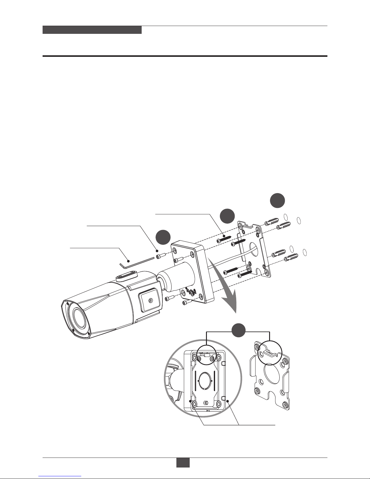
Installation Instructions
09
MEGA-PIXEL NETWORK CAMERA
1. Locate the mounting template at the installation position and drill the ceiling or
wall if needed. ( *The easy bracket can not be installed on the ceiling)
2. Place the easy bracket on pre-drilled position and fix it through using mounting
screws(4x30mm). Skip this step when an easy bracket is not installed.
3. Route the power cable to the connecting place.
Hook up the camera bracket with the easy bracket as illustrated below.
4. Fix the camera bracket through using assembly screws (4x15mm).
5. Set the camera’s viewing angle.
6. Put the sunshield to the camera unit and tighten the sunshield-bolts.
Torque Wrench
Assembly Screw
: 4x15mm
Mounting Screw
: 4x30mm
REAR VIEW
1
2
3
4
Cable exit
Installation Instructions
10
MEGA-PIXEL NETWORK CAMERA
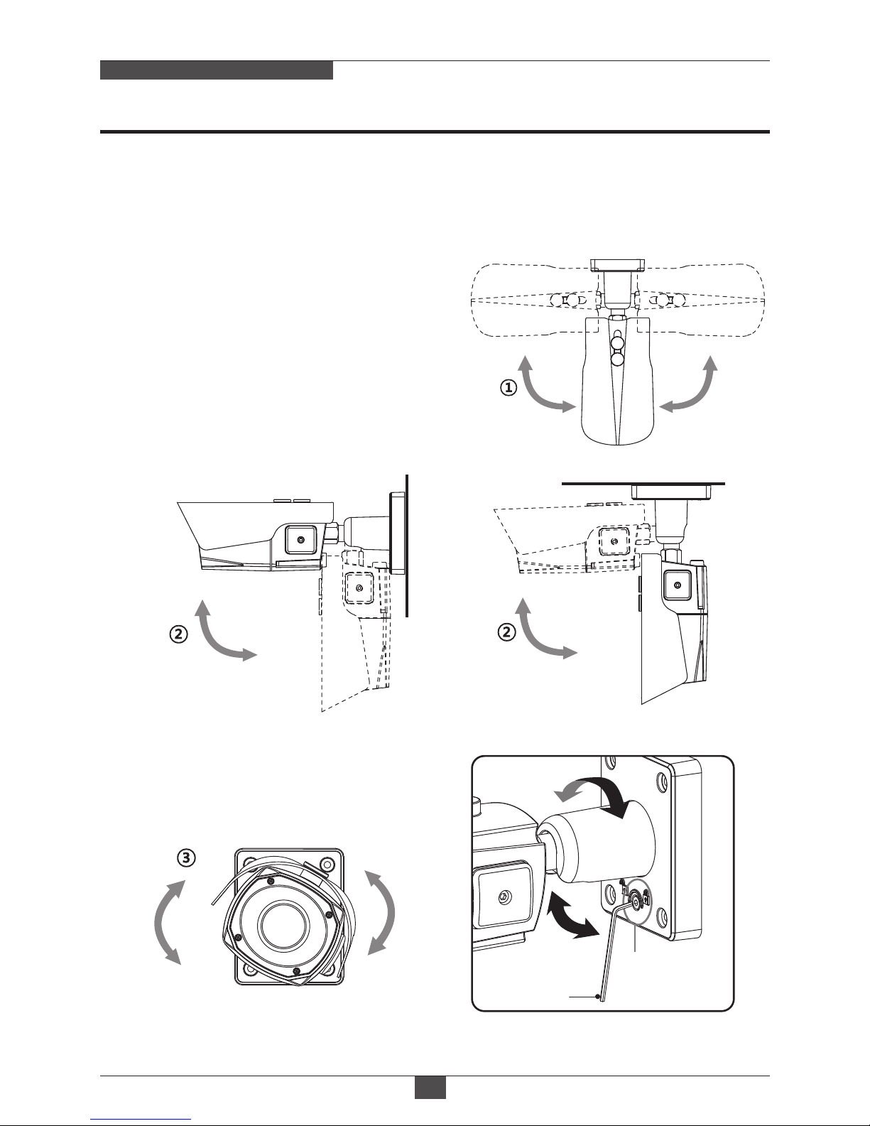
• Unlock the screw on the camera bracket through using the torque wrench supplied
• Set the camera’s viewing angle then lock the screw on the bracket.
Pan & Tilt adjustments
1) Pan limit:
Pan is limited to +/- 90°.
3) Inclination limit
(Horizontal image alignment):
Inclination limited to +/-90° max.
2) Tilt limit:
Tilt is limited to 0°(2°) min ~ 90° max.
for wall(ceiling) installation respectively
with reference to the wall(ceiling) when
the inclination of camera module is 0°,
that is, the image is aligned horizontally.
90° 90°
88°
90°
±90°
• on the wall • on the ceiling
■Adjustment of viewing angle with a bracket
Torque
wrench
Lock/Unlock
Screw
Table des matières
Autres manuels Ronix Caméra de sécurité


