REXROTH VFC 5610 Manuel utilisateur

The Drive & Control Company
Rexroth Frequency Converter
VFC 3610 / VFC 5610
Edition 06
Quick Start Guide
R912005518
Bosch Rexroth AG VFC 3610 / VFC 5610
Record of Revision
Edition Release Date Notes
DOK-RCON04-VFC-X610***-QU01-EN-P 2014.04 First release
DOK-RCON04-VFC-X610***-QU02-EN-P 2014.05 Model extension
DOK-RCON04-VFC-X610***-QU03-EN-P 2014.05 New functions
DOK-RCON04-VFC-X610***-QU04-EN-P 2014.06 New functions
DOK-RCON04-VFC-X610***-QU05-EN-P 2014.08 New functions
DOK-RCON04-VFC-X610***-QU06-EN-P 2014.11 New functions
Introduction of this Documentation
This Quick Start Guide is derived from the Operating Instructions which in-
cludes the product data in details.
Personal injury and property damage caused by
incorrect application, installation or operation!
WARNING
Never work with or control the product before reading through
●Safety Instructions in the standard delivery
●Safety descriptions in the Operating Instructions
Reference
For documentations available in other type or language, please consult your lo-
cal sales partner or check www.boschrexroth.com/vfcx610.
Copyright
© Bosch Rexroth (Xi'an) Electric Drives and Controls Co., Ltd. 2014
This document, as well as the data, specifications and other information set
forth in it, are the exclusive property of Bosch Rexroth (Xi'an) Electric Drives
and Controls Co., Ltd. It may not be reproduced or given to third parties without
its consent.
Liability
The specified data is intended for product description purposes only and shall
not be deemed to be a guaranteed characteristic unless expressly stipulated in
the contract. All rights are reserved with respect to the content of this documen-
tation and the availability of the product.
RS-ed5e7bee01562bdb0a6846a50013e6d6-6-en-US-4

Table of Contents
Page
1 Mechanical Installation.......................................................................... 1
1.1 Visual Check.......................................................................................... 1
1.2 Ambient Conditions............................................................................... 1
1.3 Installation Conditions........................................................................... 2
1.4 Figures and Dimensions......................................................................... 3
1.4.1 Figures................................................................................................... 3
1.4.2 Dimensions............................................................................................ 4
1.4.3 DIN Rail Mounting.................................................................................. 5
2 Electric Installation................................................................................ 6
2.1 Overview of Electric Connections.......................................................... 6
2.2 Cable Specifications.............................................................................. 7
2.2.1 Power Connection................................................................................. 7
Cable specification for international without USA / Canada................. 7
Cable specification for USA / Canada.................................................... 8
2.2.2 Control Signal Connection..................................................................... 9
2.3 Terminals............................................................................................. 10
2.3.1 Power Terminals.................................................................................. 10
2.3.2 Control Terminals................................................................................ 11
Control terminals figure....................................................................... 11
Control terminals description.............................................................. 12
Digital input X1...X5 NPN / PNP wiring................................................ 14
Digital output DO1a, DO1b load pull-up / pull-down wiring................ 15
Analog input terminals (AI1, AI2, +10 V, +5 V, Earth and GND)............ 15
3 Start-up................................................................................................ 16
3.1 LED Panel and Dust Cover................................................................... 16
3.1.1 LED Panel............................................................................................ 16
3.1.2 Dust Cover........................................................................................... 17
3.1.3 LED Indicator....................................................................................... 18
3.1.4 Operating Descriptions........................................................................ 19
3.2 Start-up Procedure.............................................................................. 20
3.2.1 Checking before Power-on................................................................... 20
3.2.2 Checking after Power-on...................................................................... 20
3.2.3 Checking Start-up Parameters............................................................. 20
3.2.4 Control the Motor................................................................................ 22
3.2.5 Motor Parameters Auto-Tuning............................................................. 23
VFC 3610 / VFC 5610 Bosch Rexroth AG
Table of Contents
DOK-RCON04-VFC-X610***-QU06-EN-P I

Page
3.3 Parameter List..................................................................................... 24
3.3.1 Terminology and Abbreviation in Parameter List................................. 24
3.3.2 Group b: System Parameters............................................................... 24
b0: Basic system parameters............................................................... 24
3.3.3 Group C: Power Parameters................................................................ 25
C0: Power control parameters............................................................. 25
C1: Motor and system parameters....................................................... 27
C2: V/f control parameters.................................................................. 28
C3: Vector control parameters............................................................. 29
3.3.4 Group E: Function Control Parameters................................................ 30
E0: Set point and control parameters.................................................. 30
E1: Input terminal parameters............................................................. 33
E2: Output terminal parameters.......................................................... 36
E3: Multi-speed and simple PLC parameters....................................... 38
E4: PID control parameters.................................................................. 40
E5: Extended function parameters....................................................... 41
E8: Standard communication parameters............................................ 42
E9: Protection and error parameters................................................... 42
3.3.5 Group U: Panel Parameters.................................................................. 44
U0: General panel parameters............................................................. 44
U1: Seven-segment panel parameters................................................. 44
3.3.6 Group d: Monitoring Parameters......................................................... 45
4 Diagnosis............................................................................................. 46
4.1 Display of LED Characters................................................................... 46
4.2 Staus Code.......................................................................................... 46
4.3 Warning Code...................................................................................... 46
4.4 Error Code........................................................................................... 47
Bosch Rexroth AG
Table of Contents
VFC 3610 / VFC 5610
II DOK-RCON04-VFC-X610***-QU06-EN-P

1 Mechanical Installation
1.1 Visual Check
After unpacking the frequency converter, perform a thorough visual check.
Check the following:
●The right device has been supplied
●The device has no damage
●No transport damage such as scratches, cracks or dents
If you find any deviation from one of the above points, please contact your
Bosch Rexroth sales partner.
1.2 Ambient Conditions
If it is to function perfectly, the frequency converter must be installed in an envi-
ronment matching the data provided below.
Rated ambient temperature -10...40 °C
Derating / ambient temperature 1.5 % / 1 °C (40...50 °C)
Rated altitude ≤ 1,000 m
Derating / altitude 1 % / 100 m (1,000...4,000 m)
Relative humidity ≤ 90 % (No condensation)
Degrees of protection IP 20 (Open type)
Degrees of pollution 2 (EN 50178)
Tab. 1-1: Ambient conditions
VFC 3610 / VFC 5610 Bosch Rexroth AG
Mechanical Installation
DOK-RCON04-VFC-X610***-QU06-EN-P 1/51
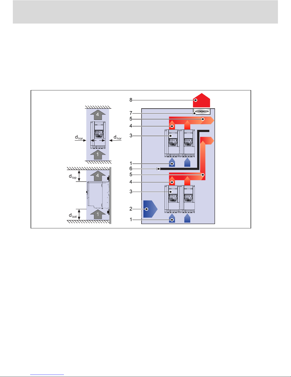
1.3 Installation Conditions
The frequency converter must be installed vertically.
If one frequency converter is arranged above another, make sure the upper limit
of air temperature into the inlet is not exceeded (see 'Technical Data' in the Ope-
rating Instructions). An air guide is recommended between the frequency con-
verters to prevent the rising hot air being drawn into the upper frequency con-
verter if the upper limit of air temperature is exceeded.
Fig. 1-1: Mounting distance and arrangement
dhor: Distance horizontal = 0 mm (allows side-by-side mounting)
dtop: Distance top = 125 mm
dbot: Distance bottom = 125 mm
1: Air inlet at frequency converter
2: Air inlet at control cabinet
3: Frequency converter
4: Air outlet at frequency converter
5: Heated air conveying direction
6: Air guide in control cabinet
7: Fan in control cabinet
8: Discharge of heated air
Bosch Rexroth AG
Mechanical Installation
VFC 3610 / VFC 5610
2/51 DOK-RCON04-VFC-X610***-QU06-EN-P
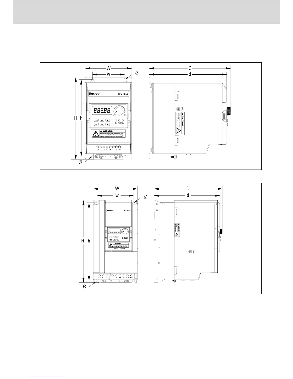
1.4 Figures and Dimensions
1.4.1 Figures
Fig. 1-2: VFC x610 0K40...4K00 dimensions figure
Fig. 1-3: VFC x610 5K50...18K5 dimensions figure
VFC 3610 / VFC 5610 Bosch Rexroth AG
Mechanical Installation
DOK-RCON04-VFC-X610***-QU06-EN-P 3/51
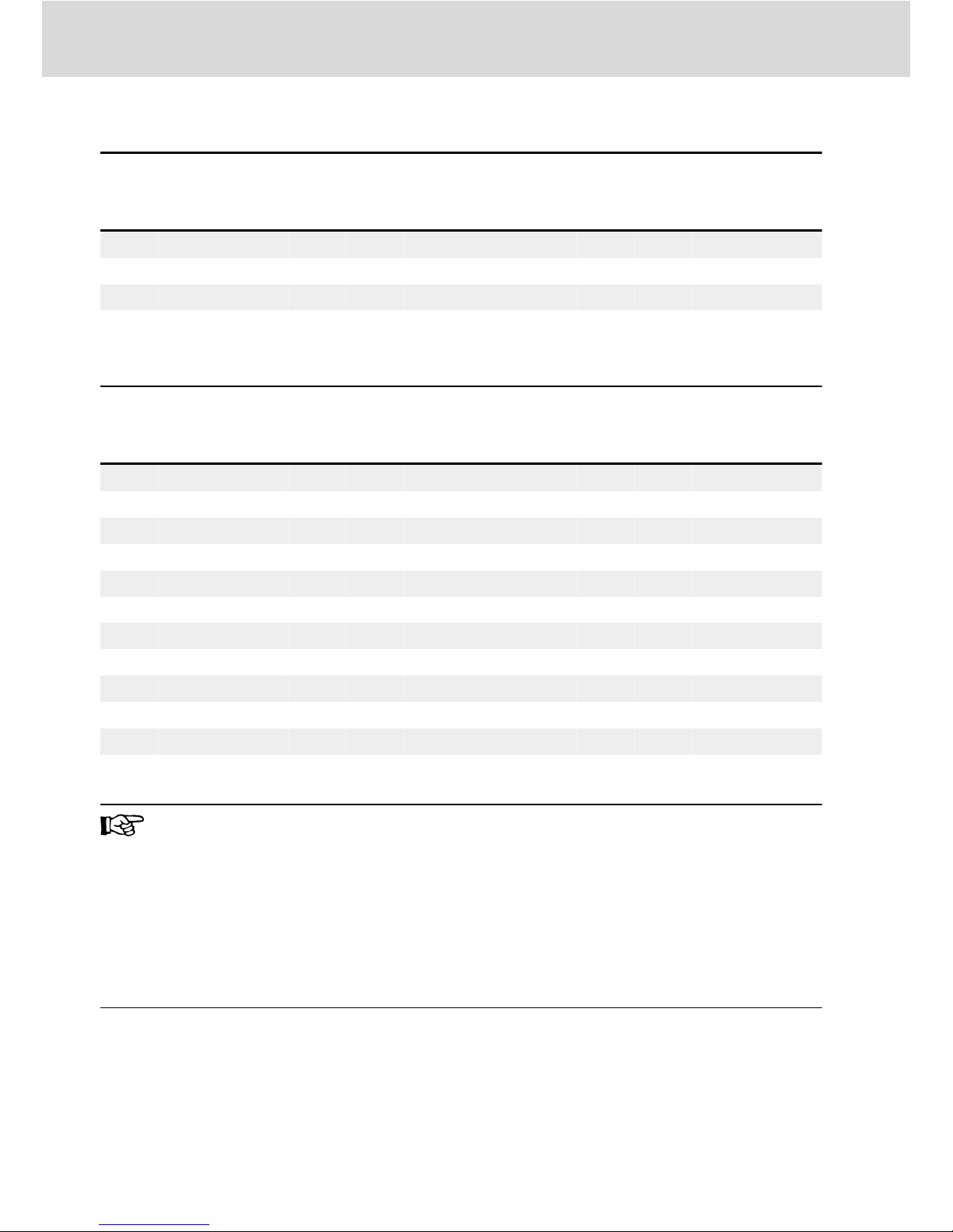
1.4.2 Dimensions
Frame Model①
Dimensions [mm] Screw
size②
Net
weight
[kg]
W H D w h d Ø
B 0K40 95 166 167 66 156 159 4.5 M4 1.5
B 0K75 95 166 167 66 156 159 4.5 M4 1.5
C 1K50 95 206 170 66 196 162 4.5 M4 1.8
D 2K20 120 231 175 80 221 167 4.5 M4 2.6
Tab. 1-2: VFC x610 1P 200 VAC dimensions
Frame Model①
Dimensions [mm] Screw
size②
Net
weight
[kg]
W H D w h d Ø
B 0K40 95 166 167 66 156 159 4.5 M4 1.5
B 0K75 95 166 167 66 156 159 4.5 M4 1.5
C 1K50 95 206 170 66 196 162 4.5 M4 1.8
C 2K20 95 206 170 66 196 162 4.5 M4 1.8
D 3K00 120 231 175 80 221 167 4.5 M4 2.6
D 4K00 120 231 175 80 221 167 4.5 M4 2.6
E 5K50 130 243 233 106 228 225 6.5 M6 3.6
E 7K50 130 243 233 106 228 225 6.5 M6 3.9
F 11K0 150 283 233 125 265 225 6.5 M6 5.0
F 15K0 150 283 233 125 265 225 6.5 M6 5.7
G 18K5 165 313 241 140 295 233 6.5 M6 7.3
Tab. 1-3: VFC x610 3P 400 VAC dimensions
●①: The complete type code for frequency converter is:
VFCx610-xKxx-xPx-MNA-xx-NNNNN-NNNN, see "Appendix: Type
Coding" in the Operating Instructions.
E.g., type code for VFC 5610 5K50 (3P 400 VAC model) is:
VFC5610-5K50-3P4-MNA-7P-NNNNN-NNNN.
●Model 3K00: ONLY available with VFC 3610.
●②: 4 screws are needed for mounting of VFC x610.
Bosch Rexroth AG
Mechanical Installation
VFC 3610 / VFC 5610
4/51 DOK-RCON04-VFC-X610***-QU06-EN-P
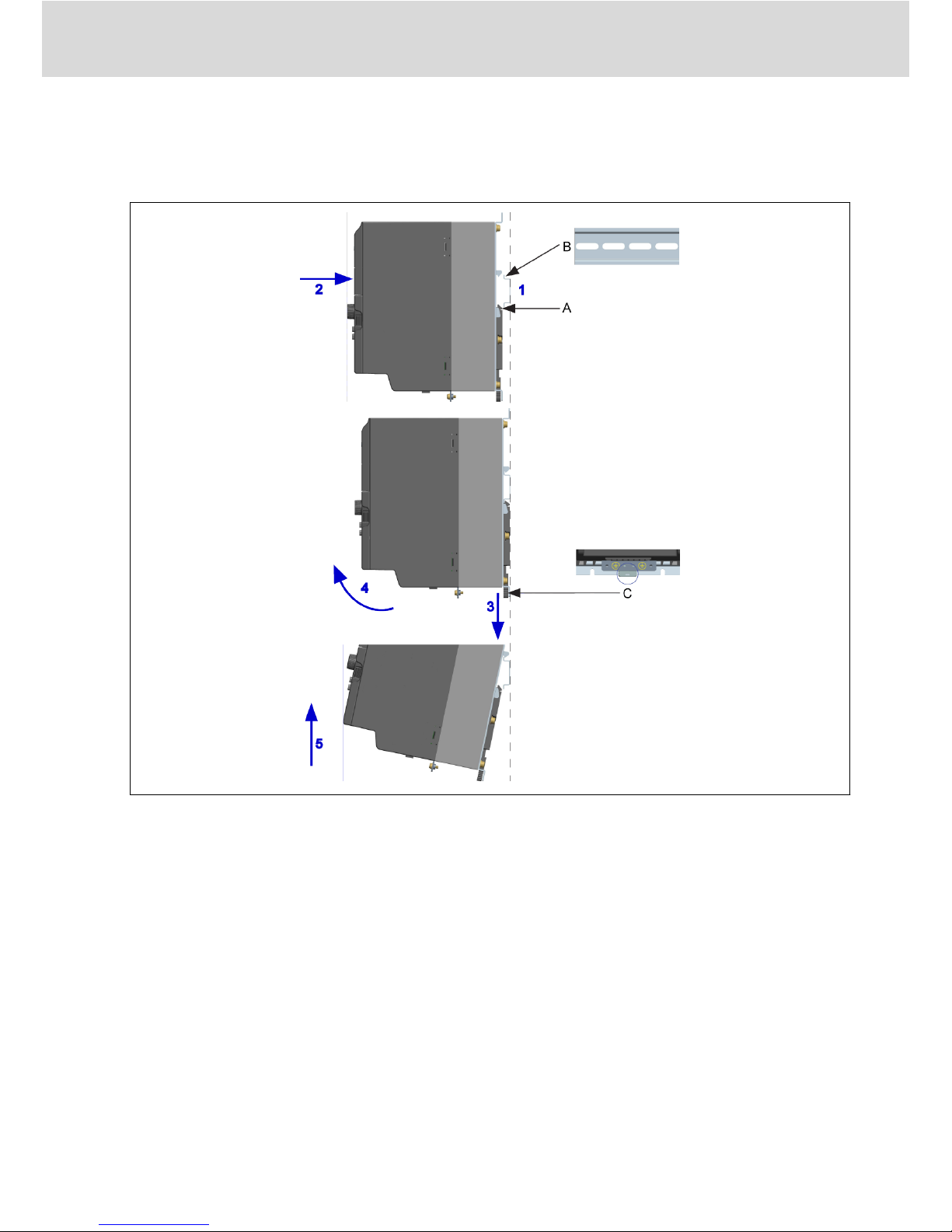
1.4.3 DIN Rail Mounting
Besides wall mounting with screws, Frequency Converter VFC x610 also pro-
vides DIN rail mounting for models 0K40...7K50.
AMounting buckle
BMounting rail
CDisassembly handle
Fig. 1-4: DIN rail mounting and disassembly
Mounting steps:
1: Hold the frequency converter and keep component A and the lower edge of
component B at the same position level.
2: Push the frequency converter horizontally till a buckle sound indicates a suc-
cessful mounting.
Disassembly steps:
3: Pull down component C and hold it.
4: Rotate the frequency converter to an appropriate angle as the arrow indi-
cates.
5: Lift the frequency converter upwards.
VFC 3610 / VFC 5610 Bosch Rexroth AG
Mechanical Installation
DOK-RCON04-VFC-X610***-QU06-EN-P 5/51

2 Electric Installation
2.1 Overview of Electric Connections
Fig. 2-1: Wiring diagram
●Information on cable size, fuse, screw torque, see chapter 2.2.
●Information on terminals, see chapter 2.3.
●①: PNP modes, see chapter 2.3.2.
●Pulse input can ONLY be set via 'Multi-function digital input X5'.
Bosch Rexroth AG
Electric Installation
VFC 3610 / VFC 5610
6/51 DOK-RCON04-VFC-X610***-QU06-EN-P
Ce manuel convient aux modèles suivants
1
Table des matières
Autres manuels REXROTH Convertisseur de média

REXROTH
REXROTH Fv Series Manuel utilisateur

REXROTH
REXROTH Fe Series Manuel utilisateur

REXROTH
REXROTH VFC 3610 Manuel utilisateur

REXROTH
REXROTH EFC3600 Series Manuel utilisateur

REXROTH
REXROTH EFC 3610 Series Manuel utilisateur

REXROTH
REXROTH FECG Series Manuel utilisateur

REXROTH
REXROTH Fe Series Manuel utilisateur


