Rewatec BlueLine II Series Mode d’emploi

BlueLine II Tank DORW2046a 26.08.2013 1 / 16
Technische Dokumentation
Unterirdische Universalspeicher BlueLine II
Technical Documentation
Underground Container BlueLine II

BlueLine II Tank DORW2046a 26.08.2013 2 / 16
1. Standort
1.1 Lage zu Gebäuden
Die Baugrube darf einen Mindestabstand zu Gebäuden nicht unterschreiten, siehe Punkt
3 Bild 1. Der Tank darf nur überbaut werden, wenn die auftretenden Lasten nicht höher
sind als die Verkehrslasten.
1.2 Verkehrsverhältnisse
Belastungsklasse A15 (z.B. Fußgänger, Radfahrer): keine besondere Ausstattung nötig.
Belastungsklasse B (PKW, Kleinbus, max. Achslast 2,2 To): siehe Einbauanleitung für
Schachtverlängerung DORW3051. Mindestabstand 600 mm zwischen Schulterhöhe Tank
und Oberkante Fahrbahnbelag.
SLW30 Belastungsklassen D (LKW max. Achslast 11,5 To): Zwischenring nötig, weitere
Information in Anleitung DORW2127 sowie Punkt 3 Bilder 10, 13 und 16. Mindestabstand
800 mm zwischen Schulterhöhe Tank und Oberkante Fahrbahnbelag.
1.3 Bodenverhältnisse
Die Tanks dürfen maximal bis zu einem Drittel ihrer „Schulterhöhe“ (siehe Abbildungen
unter Punkt 4) in Grund-/bzw. Schichtenwasser eintauchen. Bei suspendiertem
(„verflüssigtem“) Lehmboden darf die Eintauchtiefe nicht mehr als 250 mm betragen.
1.4 Hanglage
Das Gelände ist auf Rutschungsgefahr des Erdreichs zu prüfen (DIN 1054 Ausgabe
1/2003, E DIN 4084 Ausgabe 11/2002) und gegebenenfalls mit einer Stützkonstruktion
(z.B. einer Mauer) zu stabilisieren. Informationen dazu gibt es bei örtlichen Behörden und
Baufirmen.
1.5 Weitere Kriterien
Vorhandene Leitungen, Rohre, Vegetation sowie andere Besonderheiten sind so zu
berücksichtigen, dass Beeinträchtigungen und Gefährdungen vermieden werden. Die
Erdüberdeckung ab Tankschulter (Punkt 4) darf maximal 1,5 m betragen.
2. Installation
2.1 Verfüllmaterial am Tank (Umhüllung, Bettung; Punkt 3 Bilder 3,4 und 10)
Das Verfüllmaterial muss gut verdichtbar und wasserdurchlässig sein, eine feste Packung
bilden und darf die Tankoberfläche nicht beschädigen. Wenn das Verfüllmaterial
scharfkantige und/oder spitze Bestandteile enthält, ist die Tankwand durch eine
Sandumhüllung zu schützen.
2.1.1 Sand- Kiesgemische (SW und GW nach DIN 18196 und ENV 1046) sind die
günstigsten Verfüllmaterialien, da sie bei sehr geringen Feinkornanteil (Feinkorn: unter Ø
0,06mm) eine über mehrere Korngrößenbereiche verlaufende Körnungslinie aufweisen.
Bei der Bezeichnung der Gemische gibt die erste Zahl die Maschenweite (vereinfacht Ø)
des kleinsten Korns an und die zweite die des größten Korns: z.B. 0/32; 2/16; 2/8; 2/32;
4/16. Welche Gemische wo lieferbar sind, hängt stark von den regionalen Kieswerken ab.
2.1.2 Betonkies, bzw. aufbereiteter Betonschutt der Körnung 0/32 sind besonders
gut geeignet für den Einbau in lehmiger Umgebung bei Grund- Und Schichtenwasser. Bei
Grund- und Schichtenwasser ist besonders auf eine gute Verdichtung auch an schwer
zugänglichen Stellen zu achten.
2.1.3 Splitt ist gebrochenes Gestein des Körnungsbereichs 2/32 und grundsätzlich als
Verfüllmaterial geeignet; wegen seiner Scharfkantigkeit muss der Tank gegen
Beschädigungen z.B. durch eine Sandumhüllung geschützt werden.

BlueLine II Tank DORW2046a 26.08.2013 3 / 16
2.1.4 Aushub, Sand-/Kiesgemische mit lückenhafter Körnungslinie sind als
Verfüllmaterial geeignet, wenn sie den unter Punkt 2.1 aufgeführten Kriterien
entsprechen.
2.1.5 Mutterboden, Kleie, Lehme und andere bindige Böden sind für die Verfüllung
ungeeignet.
2.2 Verfüllung außerhalb der Umhüllung des Tanks
Es kann Aushub (Punkt 3 Bilder 1 und 10) oder anderes Material verwendet werden, das
ausreichend stabil und sickerfähig ist.
2.3 Verfüll- Verdichtungsmethoden
2.3.1 Die anzuwendenden Verfüll- und Verdichtungsmethoden sind in Kapitel 3
beschrieben (Installationsanleitung)
2.3.2 Zu den nicht anzuwendenden Methoden gehört insbesondere das
Einschlämmen. Es wird keine Verdichtung erreicht und das Korngemisch entmischt sich,
so dass keine stabile Packung entsteht.
2.3.3 Tragschicht befahrbare Version
Es ist Gestein des Korngrößenbereichs 2/45 zu verwenden.
2.4 Leitungen
2.4.1 Die Zulaufleitung sollte mit Gefälle zum Tank verlegt werden (>1%; Installations-
anleitung Bild 11).
2.4.2 Eine Überlaufleitung bzw. Ablaufleitung sollte ein stärkeres Gefälle vom Tank weg
aufweisen, als das der Zulaufleitung zum Tank hin (Installationsanleitung Bild 11).
2.4.3 Eine Versorgungsleitung ist so zu gestalten, dass ein Überfluten eines
angeschlossenen Aggregatraums (z.B. Keller) bei (über-)vollem Tank vermieden wird.
Dieses kann beispielsweise realisiert werden durch ein ausreichend starkes Gefälle der
Leitung vom Haus zum Tank. Oder die Installation einer Abdichtung.
2.4.4 Die Leitungen sind so einzubauen, dass Frostsicherheit gewährleistet ist. Dieses ist
entsprechend den örtlichen klimatischen Verhältnissen, gegebenenfalls in Abstimmung
mit den Behörden, festzulegen.
1. Location
1.1 Position to buildings
The excavation hole must not located within a minimum distance to buildings, see point 3
figure 1. The tank may be built over only if the appearing loads are not higher than the
traffic loads.
1.2 Traffic conditions
Loading class A15 (e.g. pedestrian, cyclist): no special equipment necessary.
Loading class B (passenger car, minibus; max. axle loading 2,2 Tonne): Technical
documentations for extension shafts DORW3051. Minimum distance from shoulder height
tank to top of the road surface: 600 mm.
SLW30 loading class D (lorry; max. axle loading 11,5 Tonne): spacer ring necessary,
further information in manual DORW2127 as well as point 3 figures 10, 13 and 16.
Minimum distance of 800 mm between shoulder height of tank and top edge of road
surface.
1.3 Ground conditions
The tanks may be installed up to a maximum of one third of their "shoulder height" (see
figures under point 4) in ground water respectively layer water. With suspended
("liquefied") clay/silt ground the depth may not exceed 250mm.

BlueLine II Tank DORW2046a 26.08.2013 4 / 16
1.4 Hillside situation
The soil of the area has to be checked for possible soil movement (DIN 1054 edition
1/2003, E DIN 4084 edition 11/2002) and if necessary it will need to be secured with a
supporting structure (e.g. a wall). Further information is available at the local public
authorities and building enterprises.
1.5 Further criteria
Existing pipelines, pipes, vegetation as well as other specifics have to be considered, so
that damage or hazards will be avoided. The soil coverage from the tank shoulder (point
4) may not exceed 1.5 m.
2. Installation
2.1Backfill material at the tank (backfill, bedding; point 3 figures 3, 4 and 10)
The backfill material has to be well compactable and permeable to water, allowing close
packing and no damage the surface of the tank. If the filling material contains sharp or
sharp-edged components, the wall of the tank has to be protected by a sandy coating.
2.1.1 Sand - gravel mixtures (SW and GW to German Institute for Standardization
18196 and ENV 1046) are the most favourable filling materials, because they have a
grain line which consists of several grain sizes with only a low amount of fines (fines:
under Ø 0,06mm). At the description of the mixtures the first number gives the mesh
width (simplified Ø) of the smallest grain and the second one those of the biggest grain:
e.g., 0/32; 2/16; 2/8; 2/32; 4/16. Which mixtures are available, strongly depends on the
regional gravel plants.
2.1.2 Concrete gravel, or treated concrete rubble, with a particle size of 0/32 mm is
particularly well suited for use in clay/loam soil conditions with ground water and a high
water table. When ground water and a high water table are present, it is particularly
important to ensure good compaction, especially at hard to reach places.
2.1.3 Stone Chippings - crushed rock particles between 2/32 mm in size and is
primarily suited as a filling material; however due to its sharp edges, the tank must be
protected against damage, for example using a sand coating.
2.1.4 Excavation, sand and gravel mixture with mixed particle sizes is suitable for
use as a filling material when it meets the criteria listed under Item 2.1.
2.1.5 Top soil, clay, loam and other types of cohesive soils are not suitable filling
materials.
2.2 Filling beyond the backfill
Excavated soil (point 3 figures 1 and 10) or other material can be used if this is stable
and permeable.
2.3 Backfilling and compaction methods
2.3.1 The backfilling and compaction methods to be used are described in Section
3 (Installation instructions)
2.3.2 Methods that are not to be used include in particular adding water. Adequate
compaction is not achieved and the mixture of particle sizes combine in such a way that
the compaction is unstable.
2.3.3 Base layer (driveable version)
Range of grain size 2/45 is to be used.

BlueLine II Tank DORW2046a 26.08.2013 5 / 16
2.4 Pipes
2.4.1 The feed pipe should be laid with a fall to the tank (>1%; installation guide figure
11).
2.4.2 The overflow / drain pipe should have a deeper fall away from the tank than the
fall from the feed pipe to the tank (installation guide figure 11).
2.4.3 The service pipe is to be installed to prevent any flooding from the tank entering
the service room (e.g., cellar) if the tank is full. This can be achieved, for example, by a
high enough incline of the pipe from the house to the tank. Or by the installation of a
seal.
2.4.4 The pipes have to be installed in such a way that frost damage is avoided. This is
to be arranged according to the local climatic circumstances, if necessary in co-ordination
with the local authorities.

BlueLine II Tank DORW2046a 26.08.2013 6 / 16
3. Installationsanleitung / Installation guide
Hinweis auf weitere Informationen in Kapitel
Notes for further information in chapter

BlueLine II Tank DORW2046a 26.08.2013 7 / 16
WICHTIG: Zu Beginn des Einbaus nur
mit 500L Wasser befüllen, dann weiter
um den Tank verfüllen (siehe nächste
Seiten
IMPORTANT: To start the installation,
fill the tank only with 500L water. Than
you may continue backfilling (see next
pages)

BlueLine II Tank DORW2046a 26.08.2013 8 / 16

BlueLine II Tank DORW2046a 26.08.2013 9 / 16
BlueLine II Tank DORW2046a 26.08.2013 10 / 16
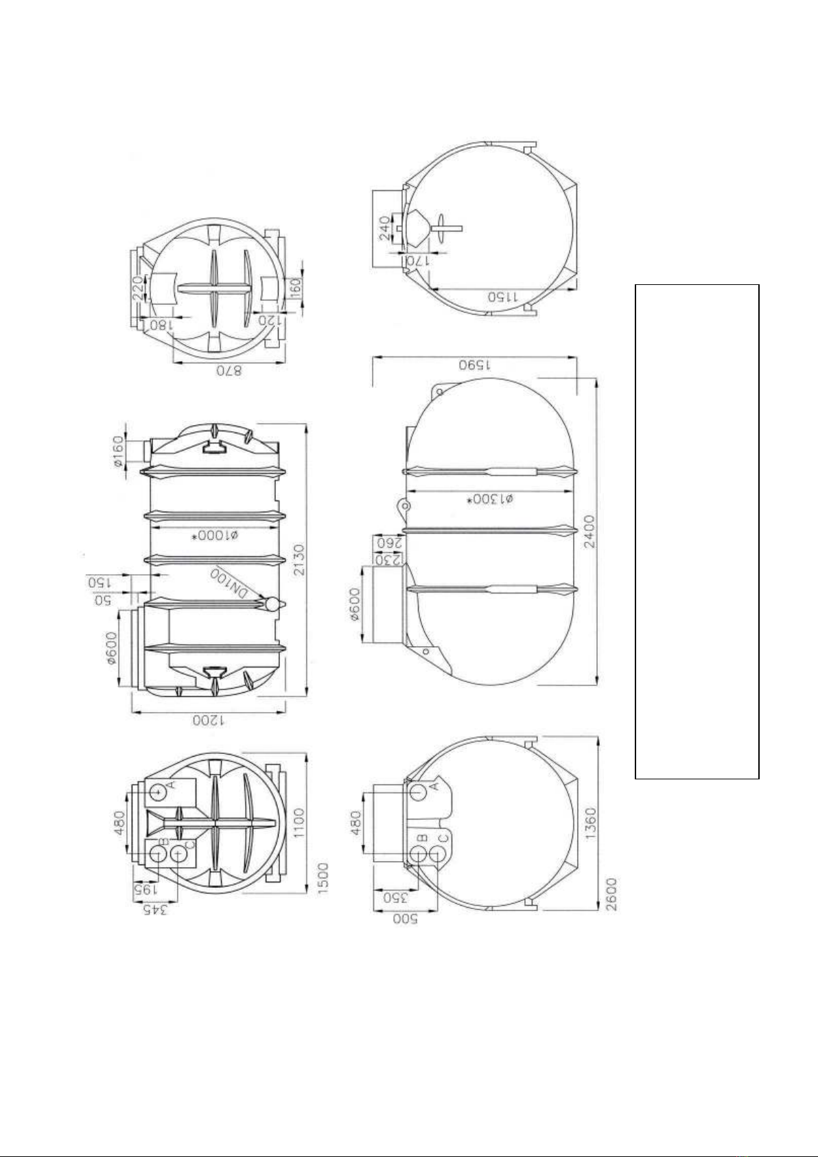
4. Hauptabmessungen und Lage der Standard-Anschlussöffnungen
Main dimensions and positions of the standard connections
A Regenwasserzulauf DN 100 / A Connection inflow DN 100
B Versorgungsrohr DN 100 / B connection service pipe DN 100
C Überlauf DN 100 / C connection overflow DN 100
* Höhe Tankschulter
* height tank shoulder
Ce manuel convient aux modèles suivants
6
Autres manuels Rewatec Chauffe-eau

Manuels Chauffe-eau populaires d'autres marques

Kenmore
Kenmore 153.582400 Manuel utilisateur

Applimo
Applimo Edel AIR Manuel utilisateur

STIEBEL ELTRON
STIEBEL ELTRON Eltronom SHU 5 S Manuel utilisateur

clage
clage E-Mini Series Manuel utilisateur

Toyotomi
Toyotomi Oil Miser OM-180 Manuel utilisateur

Bradford White
Bradford White EF Series Manuel utilisateur


 Guide de dépannage")


