Redwood RWC7100A Manuel utilisateur

RWC7100A
RF SHIELDING ENCLOSURE
Operation Manual
R211216_1.10

The information in this document is subject to change without notice and does not represent a commitment on the part of
RedwoodComm. Please visit redwoodcomm.com/Download for updates.
CONTENTS
I. Information 2
1.1. Warranty Policy 2
1.2. Key Features 3
1.3. Specifications 4
II. Operation 6
2.1. Identification of RWC7100A 6
2.2. Performance Test 7
2.2.1 How to Set up the Equipment Required for RF Shielding Effectiveness Test 7
2.2.2 Test Procedure 8
2.2.3 An Example Test Result of RF Shielding Effectiveness 9
2.3. Maintenance 10
2.3.1 Recommended Routine Maintenance and Method 10
2.3.2 Recommended EMI Gasket replacement Period 10
2.3.3 How to Replace EMI Gasket 11
III. IO Modules 12
3.1. Ordering Information 12
3.2. Example of ordering 14
Appendix 15
A.1. Performance of RWC8201A for LoRaWAN bands 15
RedwoodComm Co., Ltd. | RWC7100A Operation Manual Page 1 of 16

I. Information
1.1. Warranty Policy
RedwoodComm's RF Shielding Enclosure products are warranted for one year from the date of shipment under normal
use. During the warranty period, if it proves to be defective in its materials or workmanship, at RedwoodComm's opinion,
it will be repaired or replaced in accordance with the terms of this warranty.
The warranty covers manufacturing defects only. Consumable accessory items such as EMI foam gaskets, antenna and
cables are not included.
The liability of RedwoodComm (or its appointed maintenance agent) is limited to the cost of repair and/or replacement of
the product under warranty and invalidated in the following cases:
• If the defect is caused (howsoever) by misuse, neglect, tampering and/or incorrect adjustment.
• If unauthorized persons carry out any alterations and/or repairs.
• Where any ancillary equipment not furnished or recommended by RedwoodComm causes problems or damage that is
attached to or used in connection with the product.
• Where any additional parts/equipment that is not authorized by RedwoodComm was added and caused problems or
damage.
• If the serial number is missing on the product.
For warranty service or repair, customers must notify RedwoodComm of the defect before the expiration of the warranty
period and make suitable arrangements for the performance of service.
This warranty is valid only to the original purchaser of the product.
To obtain technical assistance or to book a service/repair for your product under warranty, please contact our customer
support. Our engineers (or agent) will support you through video calls, email, phone or in-person visit.
Contact Information
• Address: RedwoodComm Co., Ltd.
#14008, OfficeSection Bld, SK M-city, 195, Baengma-ro, ilsandong-gu, Goyang-si, Gyeonggi-do, Korea
• Tel: +82-70-7727-7011
• email: support@redwoodcomm.com or sales@redwoodcomm.com
• Online: www.redwoodcomm.com
RedwoodComm Co., Ltd. | RWC7100A Operation Manual Page 2 of 16

1.2. Key Features
The RWC7100A RF shielding enclosure offers excellent shielding effectiveness of over 100dB within a wide operating
frequency range of 400MHz to 6400MHz, so that the effects of external interference are reduced to a minimum.
In all interior workspaces, absorber material is attached in order to minimize RF reflections.
Users can utilize the three I/O panels differently depending on the purpose of use, and can order a standard I/O panel
(Module) or a separate customization panel.
To maintain lasting shielding effectiveness, users can order additional EMI gaskets and easily replace them when
necessary.
There are many kinds of wireless standards in various industries that require a strict level of shielding effectiveness.
In particular, this product is suitable for measuring radiation of various DUTs (devices under test) in development,
production line and QC applications where high accuracy is required as shown below.
LTE, NB-IoT devices (700MHz, 2-6GHz)
LoRa, Sigfox devices (400MHz, 900MHz, 2.4GHz)
WiFi devices (2.4GHz, 5.8-6.2GHz)
Bluetooth devices (2.4GHz)
GNSS devices(1.2-1.6GHz)
RedwoodComm Co., Ltd. | RWC7100A Operation Manual Page 3 of 16

1.3. Specifications
Shielding effectiveness
400MHz to 6.4GHz
≥100 dB
• Shielding effectiveness measurements taken with blank module panels mounted.
• For shielding effectiveness measurement data for each module, please refer to the 3.1 Ordering Information.
• For more detail on the test method, please refer to the 2.2. Performance Test.
• For details on maintaining the shielding effectiveness, please refer to the 2.3. Maintenance.
Dimensions and Weight
Dimensions, W x D x H mm (inches)
Interior (workspace)
260 x 190 x 100 (10.2” x 7.5” x 3.9”)
Exterior
355 x 270 x 185 (14.0” x 10.6” x 7.3”)
Weight
approx. 8.5 kg
Packing, W x D x H mm (inches)
Double packing size
450 x 350 x 270 (17.7” x 13.8” x 10.6”)
Weight
approx. 10.5 kg
(Weight and size may vary depending on the package)
Accessories list
Operating Manual
Test Report
For accessories according to other modules, please refer to the 3.1 Ordering Information.
RedwoodComm Co., Ltd. | RWC7100A Operation Manual Page 4 of 16

Environmental conditions
Temperature range
operating temperature range +20 °C to +30 °C
storage temperature range –10 °C to +50 °C
Damp heat
75 % relative humidity, non condensing at +10 °C to +30°C
• Refrain from using this equipment in a place subject to much vibration, direct sunlight, outdoor and where
the ground is not flat.
• If this product is not used for a long time, store it in a dry place away from direct sunlight, covered with vinyl or
placed in a cardboard box.
• If this product is left with the lid closed for a long time, the performance of the shield gasket may deteriorate.
Before using it again, be sure to open the lid and keep it open for at least one day, then check the shielding
effectiveness.
RedwoodComm Co., Ltd. | RWC7100A Operation Manual Page 5 of 16

II. Operation
2.1. Identification of RWC7100A
[Figure 2-1] Component Identification of RWC7100A
① 2 x M3 Hole (DP 5mm) : M3 screw holes for cable fixing
② N type Antenna Port : Additional RF port for RWC8201A antenna
③ Door (Lid) : Manual method to open/close the door from the top
④ 4 x M3 Hole (DP 8mm) : Mounting position for RWC8201A only
⑤ EMI Mesh Gasket : This detachable part is for obtaining optimal RF shielding.
⑥ 2set x EMI Foam Gasket : This detachable part is for obtaining optimal RF shielding.
⑦ Absorber : Absorbers are attached to minimize RF reflections.
⑧ Latch : Door latch handle
⑨ Hinge : Door Hinge
⑩ 4 x M4 Hole (DP5mm) : M4 screw holes for the enclosure fixing.
RedwoodComm Co., Ltd. | RWC7100A Operation Manual Page 6 of 16
2.2. Performance Test
This product is a precision RF Shielding Enclosure manufactured to be robust. Please refer to the test procedure for
shielding effectiveness below to ensure optimal performance at all times. This product may need calibration
depending on the number of uses and period of use. Please refer to the Maintenance section for more details.
This product may require maintenance depending on the number of the lid’s opening and closing and the period of
use. Please refer to the maintenance section for more details.
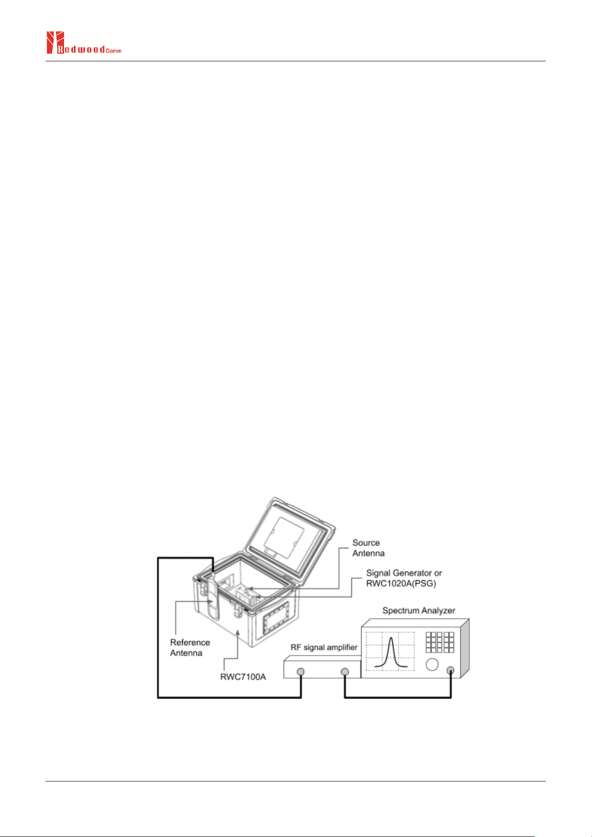
2.2.1 How to Set up the Equipment Required for RF Shielding Effectiveness Test
The following devices are required to check the shielding effectiveness.
- Signal generator : capable of generating 400M-6400MHz tone signal
- Signal generator side antenna : omni-directional one
- Signal power meter : A spectrum analyzer or equivalent device that can measure the tone power of a signal source
- Signal receiving side antenna(Reference) : A broadband antenna with high gain characteristics that can receive even
weak signals well
- RF signal amplifier : capable of sufficiently amplifying weak RF signals, if necessary
When measuring the shielding effectiveness of RWC7100A, it is recommended to install a signal generator with a
built-in battery inside RWC7100A, and perform the measurement outside of RWC7100A. If a signal is generated from
the outside and input through a cable, it is not guaranteed that the test results would be accurate.
Refer to Figure 2-2 for cable connections for testing.
[Figure 2-2] Test Setup with RWC7100A
RedwoodComm Co., Ltd. | RWC7100A Operation Manual Page 7 of 16
2.2.2 Test Procedure
1) Set up the source antenna with RWC1020A inside the RWC7100A to be located in the center.
2) Connect the spectrum analyzer and reference antenna with RF cable. (If necessary, use an adequate RF amplifier
together.)
3) Set up the spectrum analyzer as follows:
- Center Frequency: 400.1MHz (Change to 900.1MHz, 2400.1MHz, 5800.1MHz, respectively)
- Span: 500Hz
- Resolution BW: 4.7Hz (or Auto)
- Reference Level: 0dBm
- Scale 20 dB/div
4) Set up the signal generator or RWC1020A as follows:
- Frequency : 400.1MHz
- Power : +10dBm
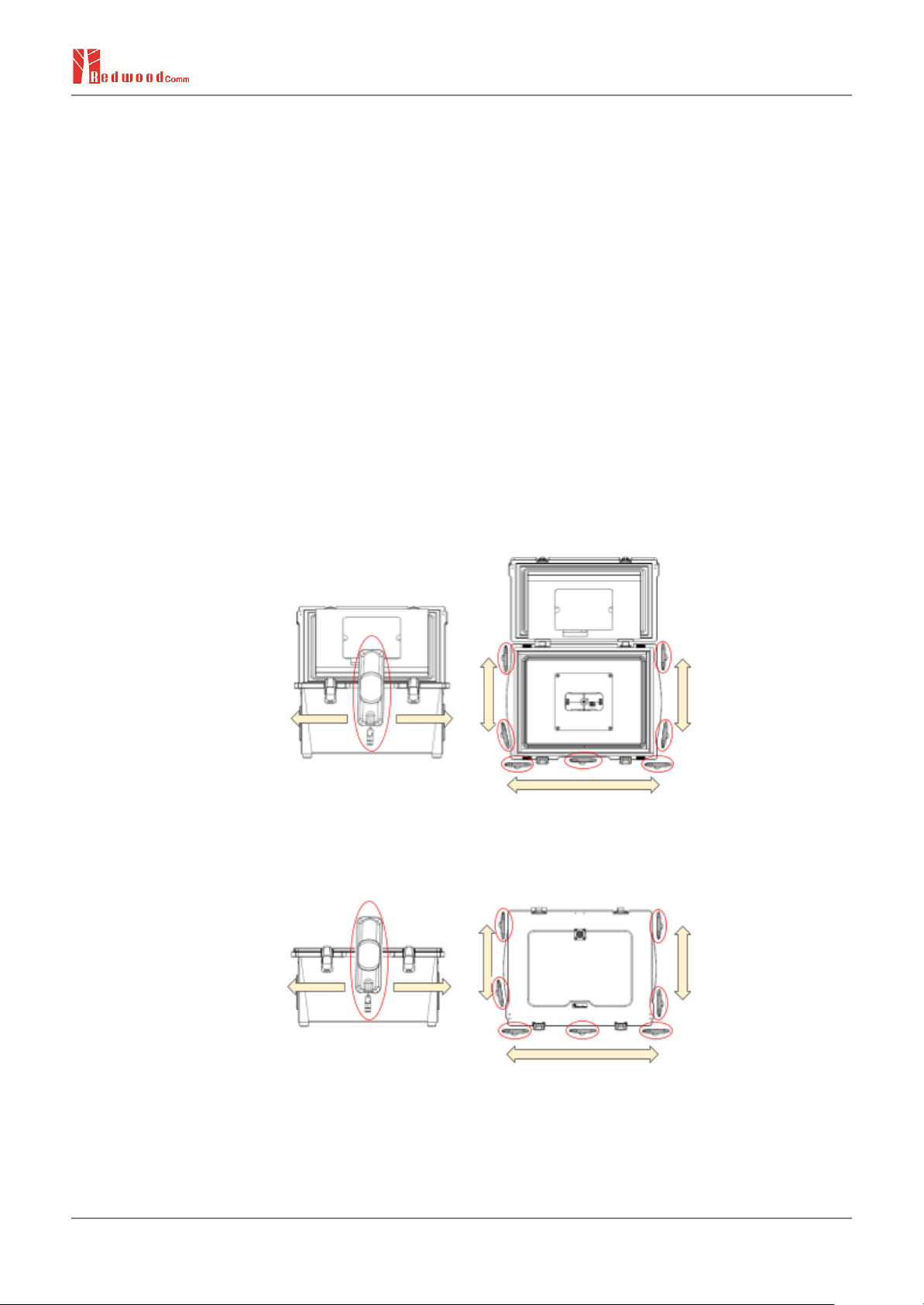
5) Open the RWC7100A door and measure the power (Pref) moving the reference antenna to several points as
shown in Figure 2-3.
[Figure 2-3] Check the reference power level (Door Opened)
6) Close the RWC7100A door and measure the output power(Pmes) moving the reference antenna at the same
positions in step 5)
[Figure 2-4] Check the measure power level (Door Closed)
7) Calculate the Shielding Effectiveness Pse[dB] = Pmes[dBm] - Pref[dBm].
8) Change the signal generator to the next frequency and repeat the measurement process, step 3) to 7)
RedwoodComm Co., Ltd. | RWC7100A Operation Manual Page 8 of 16

2.2.3 An Example Test Result of RF Shielding Effectiveness
The product conformity test was measured using a method modified from the IEEE-STD-299.1 standard.
[Figure 2-5] Shielding effectiveness of RWC7100A
RedwoodComm Co., Ltd. | RWC7100A Operation Manual Page 9 of 16
Table des matières


 Manuel utilisateur")


