RedBack Laser PL650 Manuel utilisateur


CONTENTS
User Safety 2
Introduction and PL650™ Accessories 3
PL650™Diagram 4
Operating Instructions 6
Batteries 6
Power and Grade Setting 7
Centering Dot Left to Right 8
Out of Level Warning 9
Using Feet and Target 10
Optional Tripod Mount 11
Grade Conversion Chart 12
Calibration Self Check & Technical Specications 13
Care & Maintenance, Trouble Shooting 14
Warranty 16
User Safety
• Laser output sign lies near the output aperture.
• Do not stare directly into laser beam.
• Do not disassemble the instrument or attempt to
perform any internal servicing. Repairs and service
should be performed only authorised service
centres of Redback Lasers.
• This instrument complies with the safety
Classication standards of laser radiation.
2
CAUTION: Class 3R laser <5mW at
635-670nm.
Do NOT stare into laser beam or aim
at another person.
Follow relevant Australian Standards
Copyright © CMI LasersTM RedBack lasersTM and Level1LasersTM . All rights reserved CMI Industries Pty Ltd 2010
No artwork or photographs produced by CMI Industries Pty Ltd may be used copied or reproduced without the written consent
from CMI Industries Pty Ltd

3
PL650TM INTRODUCTION
Congratulations on purchasing the PL650™ an electronic self levelling pipe
grade laser level built tough with full cast metal housing and sealed water
tight (IP68).
The PL650™ has been designed and built specically for plumbers and
drainage contractors for levelling and grading pipes.
The PL650™ has fully automatic digital grade setting to 3 decimal places
-20.000% to +40.000% range. Simply enter in the desired grade and the
laser does the rest.
The PL650™ also features laser dot centering which can be accessed either
by the control panel or remote control.
The PL650TM can be placed either on top of the pipe or inside and comes
with a selection of feet allowing the laser to t into pipes 150mm to 500mm
diameter. The PL650 also comes with a heavy duty target and holder again
designed for tting within pipes 150mm to 500mm diameter. The PL650 is
tted with a rechargeable Ni-mh battery pack but can also use Std “D” Size
batteries if needed and comes with a Two Year Redback Lasers Warranty.
(See page 16)
www.redbacklasers.com.au
PL650™ Included Accessories
• PL650™ Pipe Laser Unit
• Protective Carry Case
• Rechargeable Ni-mh Battery
• Charger
• “D” Cell Battery Pack
• Remote Control
• Targets and Holder (150mm-500mm)
• 5 Sets Feet (200mm-500mm)
• Handle Mount Foot Adaptor
• Instruction Manual

4
PL650TM DIAGRAMS
PL650TM Laser Unit
2
3
1. Alignment Guide Plumb Ref LED
2. Tripod Frame Mount (Optional)
3. Control Panel
4. Interchangeable Feet
5. Laser Dot Output
PL650
Back
Red
Lasers
TM
5
4
1
Laser Target
Target Holder
Bubble Vial
Pipe Size
Lock
5
www.redbacklasers.com.au
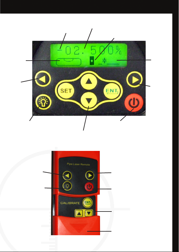
Remote Control
Control Panel
Move Laser Dot
Right Control
Power/Standby Button
Calibration Controls
(For Service Technicians Only)
Battery Compartment
Alignment Plumb
LED
% Grade to 3 Decimal Places
Battery Level Indicator
Power Button
Move
Laser Dot
Right
Level
Indicator
Left to
Right
Laser Dot
Position
Left to
Right
Alignment Plumb LED
Grade Selection Pad
Grade Direction
Move Laser Dot
Left Control
Move
Laser Dot
Right

6www.redbacklasers.com.au
PL650TM OPERATING INSTRUCTIONS
Battery Instructions
To charge this battery pack simply inserting the charger plug into the
charging socket found under the dust cover on the front of the battery pack.
The LED on the charger is illuminated red during the charging process and
will turn green once the battery pack is fully charged. The reachargeable
battery pack can be charged either whilst inserted in the laser or seperatly.
When the power symbol on the LCD shows low or ashes, the rechargeable
batteries needs recharging or standard batteries need replacing.
Handy Hints
•
Prior to initial use, charge the rechargeable battery for at least 10 hours.
•
Running rechargeable batteries completely at will increase battery life.
•
The PL650™ can operate off mains by plugging the charger (for indoor
use only) into the unit.
•
Remember the PL650™ can operate using standard batteries when
rechargeable pack is out of charge.
The PL650 has two battery options either 4 x standard “D” size Alkaline or
the Ni-mh rechargeable pack. For standard 4 x “D” alkaline operation simply
insert into the battery holder in the direction indicated, insert into laser and
tighten the locking screws.
To use the rechargeable battery
pack, remove standard battery
holder from laser if installed and
place the rechargeable pack into
the same recess and tightening
locking screws.
LCD Display Power Symbols
Battery Good Battery Needs
Charging
Flashing

7
Turning Laser On
Press Power button on the keypad to turn on the PL650™. Note
the power button on the remote will not operate until the laser has been
powered up from the keypad direct, the power button on the remote then
acts as a standby button. The PL650TM will rst have a ashing laser dot and
ashing grade numerical display, when both of these stop ashing the laser
is then level. On the bottom left of the LCD display screen is an electronic
bubble vial and an arrow indicating the direction needed to twist the PL650
Housing, within or on top of the pipe, in order to get it level left to right.
When the bubble is show in the center of the vial then it is level left to right
and will ensure maximum accuracy for the laser dot.
Setting a Grade
Setting a grade on the PL650 tilts the laser dot either up for a +ve grade
and down for a -ve grade. The grades are set as a percentage and the
maximum grade that can be set is +40.000% to -20.000%. (see page 12
for conversion chart)
The required grade is entered using the center four buttons on the key pad,
rst press the “SET” button the +/- symbol is ashing, use the up down
arrow buttons to select either a +ve or -ve grade.
Press “SET” again and the rst digit will ash, use the up and down
arrow keys to set the required number for this digit (leave as “0”
if required). To move to the next digit press “SET” once more and again use
the arrow keys. Once all the digits have been set to the required gure then
press “ENT” this enters the grade into the laser and it will begin to
set that grade. When the laser dot stops ashing the grade is set. Note the
PL650 remebers this grade the next time the laser is turned on.
Twist PL650
Clockwise
(when looking at display)
Twist PL650
Anti-Clockwise
(when looking at display)
PL650 level
left to right

8
PL650TM OPERATING INSTRUCTIONS cont.
Adjusting the Dot Left to Right
The PL650MPipe Laser dot can be adjusted left and right in order to hit the
target. This can be done with the use of either the Keypad or remote control
bu pressing the left and right arrow keys . Single presses of the
buttons move the dot by very small increments, by holding the button the
dot will move faster and the longer the button is pressed the faster the dot
will move.
On the bottom right side of the LCD display is a graphical representation of
the position of the dot left to right, the display will ash when the dot has
been moved to the maximimum allowed position.
There is an auto center feature which is activated with a single press of both
the left and right arrow buttons at the same time (note this feature
only works on the main keypad and not the remote). Whilst it is centering
the display will ash, once centered it will return to normal.
Note that the PL650 Pipe Laser has a remote control receiving sensor both at
the keypad and laser output ends of the unit making it easir to center the dot
onto the target when standing at the target end of the pipe.
www.redbacklasers.com.au
LCD Display showing the laser
dot just left of the central position

9
The PL650 has alignment marks on the side of the casing and an alignment
LED light on the top to indicate the origin point of the laser and grade. To
turn on this light simply press the light button on either the key pad
or the remote control.
www.redbacklasers.com.au
LED Alignment Guide Light
Out of Levelling Range
There may be a situation where the laser has been set to do a large Grade
which is outside the range of the laser mechanism. If this occurs a ashing
graphic will be displayed on the LCD and this graphic will indicate to either
raise or lower the control panel end of the PL650. This can be done by using
different length feet or the handle mounted foot adaptor.
LCD Display graphic showing
to raise control panel end

10
PL650TM OPERATING INSTRUCTIONS cont.
Using the Feet for Different Diameter Pipes
The PL650TM has 5 sets of feet of differeing lengths and each set has a size
printed on them which refers to the diameter size of the pipe you wish to
use the laser inside of. The idea is that with the correct size feet the laser
dot should be central to the pipe. The feet are interchanged by un-screwing
them in anti-clockwise direction. Note that when the legs are removed the
inbuilt threads are suitable for 150mm diameter pipe.
www.redbacklasers.com.au
LCD Display Light
The PL650TM has a back light for the LCD display this light activates when
any of the keys are pressed on either the keypad itself or the remote control
unit. To save battery, the light turns itself off after a few seconds of the keys
not being pressed, to turn the light back on simply press any of the keys
once more.
Using the Targets for Different Diameter Pipes
The PL650TM comes with a heavy duty target holder that can hold either the
15-300mm target plate or 400-500mm target plate. To change plates or to
adjust the height of the plate simply unlock the locking knob on the right and
slide plate up, the pointer above the knob indicates the diameter.
The Target is designed to t either inside or on top of the pipe and can be
levelled left to right with the help of the bubble vial.
Table des matières
Autres manuels RedBack Laser Instrument de mesure


Manuels Instrument de mesure populaires d'autres marques


Endress+Hauser
Endress+Hauser Proline Promag 50 Caractéristiques techniques

Siemens
Siemens SITRANS F Coriolis FCT030 Manuel de la liste des pièces

KLINGER
KLINGER CMF V Series Manuel utilisateur

EXFO
EXFO FTB-2 Manuel d'exploitation et d'entretien

Keysight
Keysight M8290A Manuel utilisateur

ADTEK
ADTEK MW-5 Manuel utilisateur