RDI PORCH RAIL Manuel utilisateur

INSTALLATION INSTRUCTIONS
• Level Rail ......................................... 2
• Stair Rail .......................................... 8
• Care & Maintenance, Finishing ...... 15
PORCH RAIL
2
A
B
C
DF
H
L
G
I
E
JK
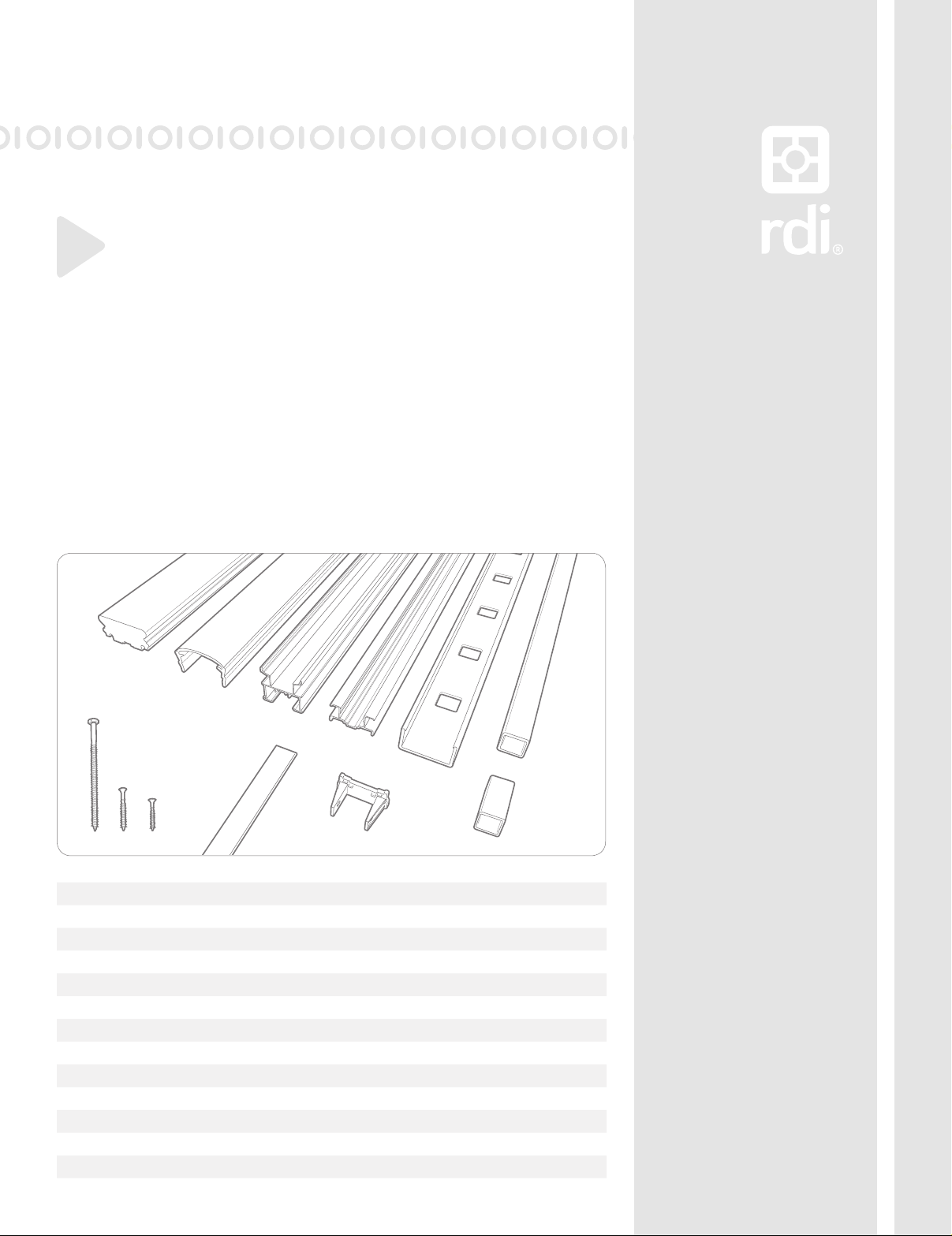
COMPONENT LIST
LEVEL RAIL KIT
Porch Rail was designed to meet the most stringent building codes. An evaluation re-
port is available through your Porch Rail Distributor or through RDI Customer Service.
COMPONENTS:
Depending on the level kit and kit length you purchased your component list will vary.
Use this as a guide to identify the individual components.
Warning:
Always wear
safety goggles.
Standard Rail Kit Wood Cover Rail Kit
A.) Wood Top Cover X Sold Separately
B.) Top Cover 1 X
C.) Top Beam 1 X
D.) Bottom Beam 1 2
E.) Beam Cover 2 2
F.) Baluster - Quantities Vary by Length-Round Iron & Glass Balusters Sold Separately
G.) Bottom Rail Support 1 1
H.) Level Mounting Bracket 4 4
I.) Screw (#12 x 5") 1 1
J.) Screw (#10 x 2") 8 8
K.) Screw (#8 x 1") 8 8
L.) Foam-Baluster Option Kits Only 2 2
3
(Fig. 1)
(Fig. 3)
(Fig. 2)
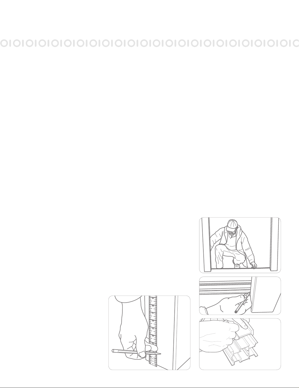
1.
Prepare all posts and mounting surfaces
before installation.
NOTE: Check with your local building
code ofce for design load requirements
for guard rails and bottom space require-
ments. All supporting structures should
be built in accordance with applicable
building codes.
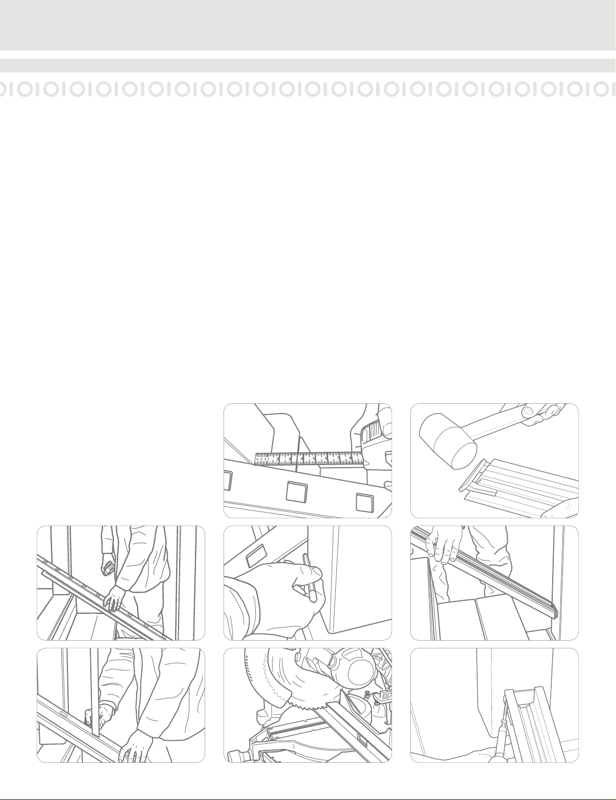
2.
Establish the level placement of the
lower rail so there is no more than a
4" space from the bottom of the rail to
the standing surface. Mark the post or
mounting surface at this dimension to
determine the bottom rail height. (See
Fig. 1)
Tip:
Standard Porch Rail measures 36" in
height with a 2" space below the bottom
rail (See NOTE in Step 1).
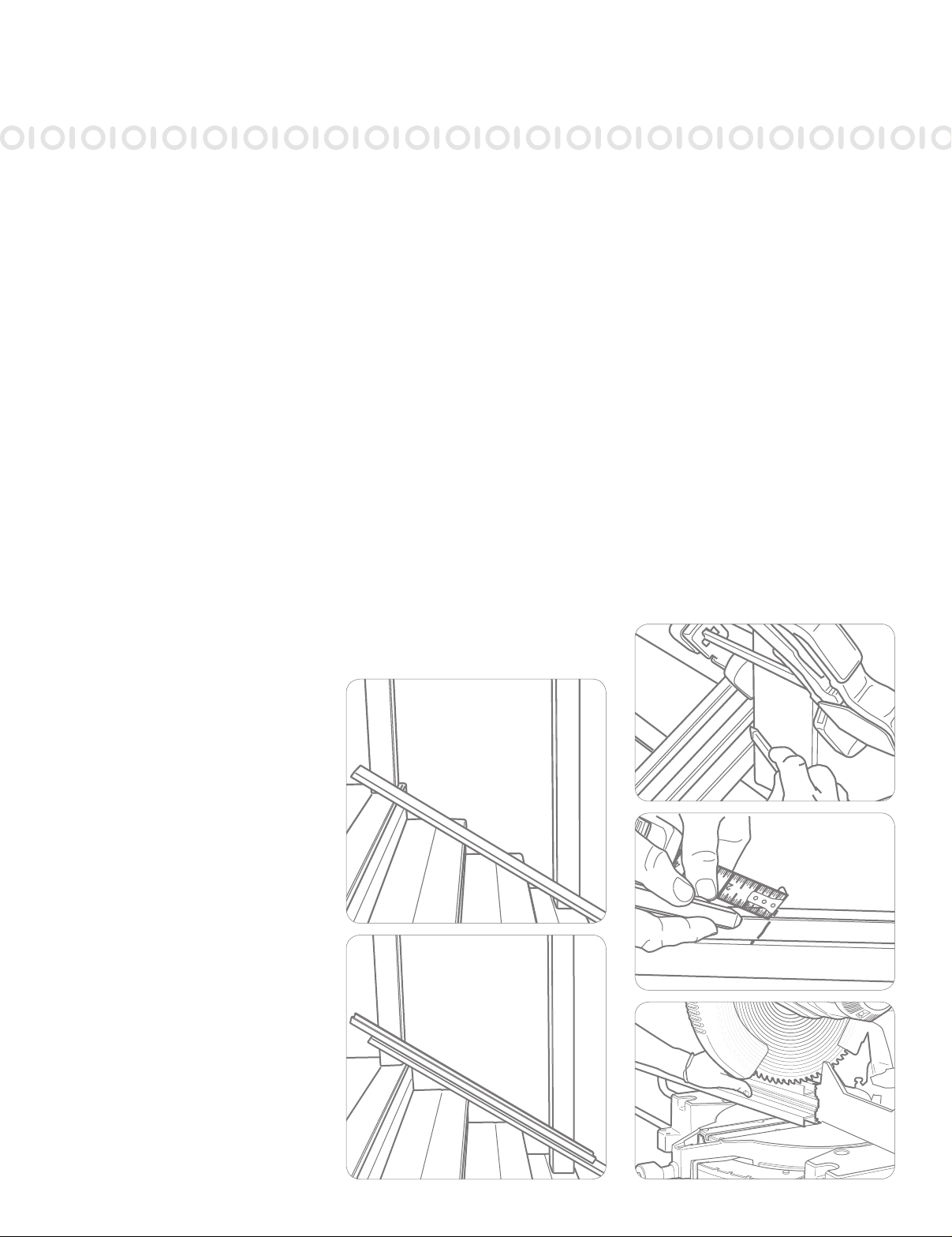
3.
Measure the nished opening space
between surfaces where the railing is to
be installed. Transfer this measurement
to the bottom beam (D) and subtract
1/2" to allow for the mounting brackets
(Fig. 2).
Tip 1:
If all of your mounting surfaces are
plumb, transfer your measurements from
the bottom beam to the top beam (C).
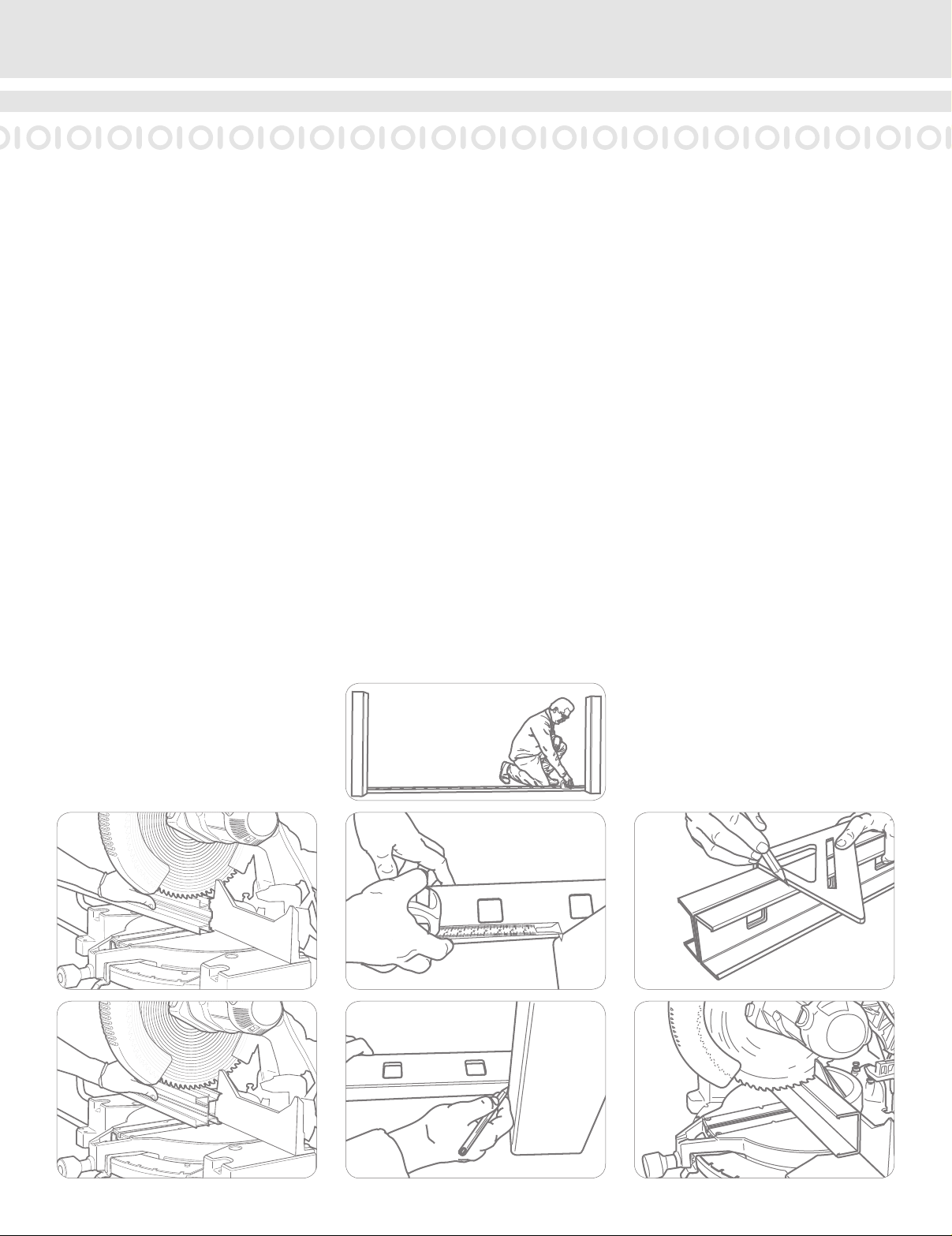
Cut the beams to the measurement
(Fig. 5, 6).
Continued on next page. >>
(Fig. 4)
STANDARD LEVEL RAIL KITS
4
(Fig. 5)
(Fig. 8)
(Fig. 7)
(Fig. 11)
(Fig. 10)
(Fig. 9)
(Fig. 6)
>> Continued from previous page.
Tip :
If using a power saw, a carbide tip blade
of at least 60 teeth is recommended.
4.
Place one of the beam covers (E) across
the opening where the railing is to be
installed (Fig. 7). Measure from the
mounting surface to the rst baluster
hole on each end (Fig. 8), and adjust
until these dimensions are equal. Trace
the post edge onto the beam cover (E) at
each end (Fig. 9).
Tip:
If all of mounting surfaces are plumb,
transfer your measurements and baluster
layout from the bottom beam cover (E) to
the top beam cover (E) (Fig. 10).
NOTE: A minimum of 1" from the edge
of the rst baluster hole to the end of the
routed beam cover (E) is necessary.

5
(Fig. 14)
(Fig. 15)
Ensure the four tabs on bracket
nest on beam as depicted. (Fig. 13)
(Fig. 12)
(Fig. 16)
(Fig. 17)
(Fig. 18)
5.
Insert mounting brackets (H) in each end
of bottom beam (Fig. 12); ensure proper
alignment (Fig. 13). Place the bottom
beam on the marks determined in
Step 2.
Secure the brackets to the post using
mounting screws (J) (Fig. 14). Secure the
brackets to the beam using mounting
screws (K).
Tip:
You can cut wood blocks to support the
bottom beam at the proper height during
installation (Fig. 15).
6.
Cut the bottom rail support (G) to the
bottom space determined in Step 2 and
place it under the bottom beam at the
center point (Fig. 16 and 17).
Pre-drill using a 1/4" dill bit for the
bottom rail support screw (I) (Fig. 18).
Secure the bottom rail support to the
standing surface with screw provided (I).

6
(Fig. 21)
(Fig. 24)
(Fig. 23)
Ensure the four tabs on bracket
nest on beam as depicted.
(Fig. 25)
(Fig. 22)
(Fig. 20)
7.
Snap the bottom beam cover (E) over
the bottom beam (D) (Fig. 20, 21).
If installing glass or iron balusters, insert
foam strip (L) into baluster channel prior
to snapping on beam cover (E).
8.
Insert a baluster (F) in each hole of the
bottom beam cover (E) (Fig. 22).
Starting at one end of the rail section,
slide the top beam cover (E) (routed at
side facing down) on top of the balusters
(Fig. 23).
Insert each baluster into the correspond-
ing rout in the top beam cover (E). Let
top beam cover (E) slide down on bal-
usters, this will be used after top beam
(C) and top cover (B) installations are
complete (See Step 11).
++++++++++++++++++++++++++++++
IF INSTALLING THE WOOD TOP
COVER (A) SKIP TO PAGE 14 OF THIS
INSTALLATION GUIDE AND THEN
RETURN TO COMPLETE STEP 12.
++++++++++++++++++++++++++++++
9.
If your top beam (C) was not previously
cut (Step 3), measure your nished
opening, deduct 1/2”, and cut.
Insert mounting brackets (H) in each end
of top beam (C) (Fig. 24); ensure proper
alignment (Fig. 25).
7
(Fig. 28)
(Fig. 27)
(Fig. 26)
(Fig. 30)
(Fig. 32)
(Fig. 31)
(Fig. 29)
(Fig. 33)
10.
Place the top beam (C), as oriented in
Fig. 25, between the posts and on top of
the balusters (Fig. 26).
Secure the brackets to the post using
mounting screws (J) (Fig. 27). Secure the
brackets to the beam using mounting
screws (K) (Fig. 28).
11.
Measure for length (Fig. 29) and cut the
top cover (B) to t (Fig. 30).
Snap the top cover (B) onto the top
beam (C) by rolling the cover to one side,
engaging the locking strip. Then, roll
the top cover (B) to the other side while
applying downward pressure. Work from
one end of the rail to the other until the
full length of the cover locks into place
(Fig. 31).
12.
Slide the top beam cover (E) up onto the
underside of the top beam (C) and snap
into place (Fig. 32, 33).

8
COMPONENT LIST
STAIR RAIL
Porch Rail was designed to meet the most stringent building codes. An evaluation re-
port is available through your Porch Rail Distributor or through RDI Customer Service.
Standard Rail Kit Wood Cover Rail Kit
A.) Wood Top Cover X Sold Separately
B.) Top Cover 1 X
C.) Top Beam 1 X
D.) Bottom Beam 1 2
E.) Beam Cover 2 2
F.) Baluster - Quantities Vary by Length-Round Iron & Glass Balusters Sold Separately
G.) Bottom Rail Support 1 1
H.) Stair Mounting Bracket 4 4
I.) Screw (#12 x 5") 1 1
J.) Screw (#10 x 2") 8 8
K.) Screw (#8 x 1") 8 8
L.) Foam-Baluster Option Kits Only 2 2
A
B
C
DF
H
L
G
I
E
JK
COMPONENTS:
Depending on the stair kit and kit length you purchased your component list will vary.
Use this as a guide to identify the individual components.
Warning:
Always wear
safety goggles.
9
(Fig. 2)
(Fig. 4)
(Fig. 3)
(Fig. 1)
(Fig. 5)
1.
Prepare all posts and mounting surfaces
before installation.
NOTE: Check with your local building
code ofce for design load requirements
for guard rails and bottom space require-
ments. All supporting structures should
be built in accordance with applicable
building codes.
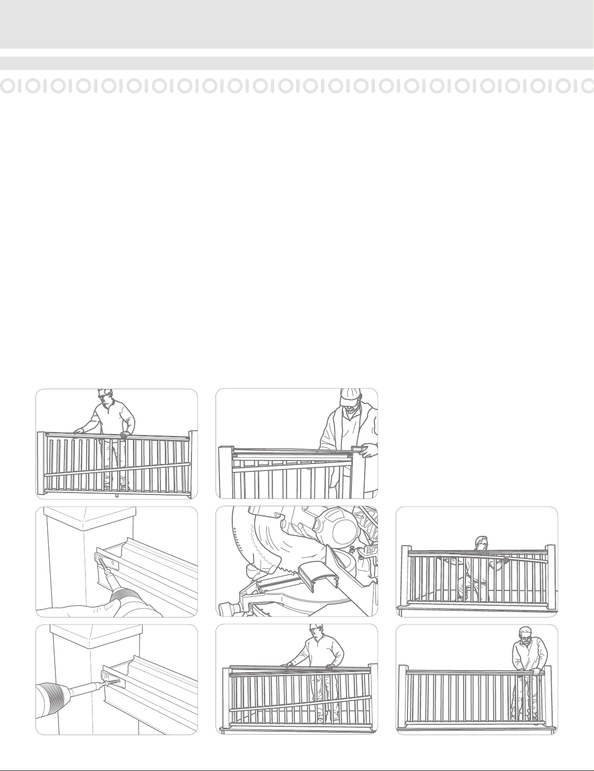
2.
Temporarily secure a plank on the nose
of the stairs along side of the posts onto
which you are installing the stair rail (Fig.
1). The thickness of the plank will deter-
mine the space between the stairs and
the bottom rail.
With the white powder coated surface of
the bottom beam facing down, place the
bottom beam (D - Oriented as shown in
the Component List) on the plank (Fig.
2). Trace the angle of the posts onto the
bottom beam (Fig. 3).
Cut the bottom beam 1/2" shorter on
one end, on the angle found in Fig. 3, to
allow for mounting brackets (Fig. 4, 5).
NOTE: Depending on the angle of your
stair, code may require you to mount
the bottom beam to the tread noses (no
plank). Check with your local building of-
ce for applicable regulations.
Tip:
If both posts are plumb you can speed
your installation by placing the top beam
(C) on top of the bottom beam with the
baluster channels facing each other, and
mark both beams at once. Then cut both
beams.
STANDARD STAIR KITS
10
4.
Insert mounting brackets (H) in each end
of bottom beam (Fig. 11); ensure proper
alignment. Set the bottom beam in posi-
tion between the posts. (Fig. 12)
Secure the brackets to the post using
mounting screws (J) (Fig. 13). Secure the
brackets to the beam using mounting
screws (K).
Tip:
A wood plank can be placed between
your posts to establish the bottom rail
space.
(Fig. 7)
(Fig. 9)
(Fig. 8)
(Fig. 6)
(Fig. 10)
(Fig. 13)
(Fig. 12)
(Fig. 11)
3.
Place a beam cover (E) on the temporary
plank (Fig. 6).
NOTE: Routed holes in the bottom beam
cover (E) are angled routs. Insure that the
bottom beam with bottom cover is facing
in the right direction to allow the balusters
to stand plumb, i.e. straight up (Fig. 7).
Slide the beam cover (E) on the plank
between the posts until the distance
from the edge of the post to the edge of
the baluster rout is the same at both the
top and the bottom (Fig. 8). Trace the
angle of the post onto the bottom beam
cover (E) at the top and bottom of the
stair (Fig. 9). Cut the beam cover (E) on
the angle traced (Fig. 10).
Tip:
If both posts are plumb you can speed
your installation by placing the top beam
cover (E) on top of the bottom cover
aligning the baluster holes. Now scribe
both covers at the same time and cut
both.
Autres manuels RDI Matériel de construction


