Radionode RN400-T2TS Manuel utilisateur

User Manual
IoT Temp Data Logger
RN400-T2TS
Keep this document nearby so that it may be referred to when needed.2021 | Rev. 1

02
Introduction Installation Operation Configuration Tapaculo 365 Maintenance Customer Service
Information
HTTP Radionode
Protocol V2 Order ListAbout this Manual
CONTENTS
About this Manual 04
Intellectual Property Rights 04
Notational Conventions 04
Introduction 05
Key Features 05
Exterior 06
Accessories 07
Specifications 08
Installation 09
Terminal Block 10
Data Logger Installation 11
Connecting Terminal Block 13
Operation 17
Viewing Channel Information 18
Viewing Device Information 19
Resetting Data Logger 20
Memory Card for Data Logging 21
Configuration 22
Device Information 24
Server 25
Measurement 26
Wi-Fi Network 28
Display 31
Commands 31
Memory Card Usage Configuration 32
Checking Communication With Tapaculo 365 Server 33

03
Introduction Installation Operation Configuration Tapaculo 365 Maintenance Customer Service
Information
HTTP Radionode
Protocol V2 Order ListAbout this Manual
Tapaculo 365 34
Adding Devices from Your Smartphone 35
Adding Devices from Your Computer 38
Maintenance 41
Cleaning 41
Batteries 41
Firmware Update 42
Customer Service Information 43
Manufacturer Contact Information 43
Warranty 43
Limit of Liability 43
Certifications 44
HTTP Radionode Protocol V2 45
Check-in 45
Data-in 48
Order List 49
Data Logger 49
Accessories 50

04
Introduction Installation Operation Configuration Tapaculo 365 Maintenance Customer Service
Information
HTTP Radionode
Protocol V2 Order List
About
this
Manual
This document contains instructions for usage and installation of
the RADIONODE®RN400-T2TS. Product specifications and certain
features herein may be subject to change without prior notice.
Figures used in this manual are for explanatory purposes only, and
may differ from your system depending on installation conditions.
Software screenshots may change after software updates.
Intellectual
Property
Rights
© 2021 DEKIST Co., Ltd.
All contents and figures herein are property of DEKIST Co., Ltd.
Reproduction or redistribution of all or part of this document in any
way is not permitted without prior consent from DEKIST.
Notational
Conventions
Failure to follow instructions marked with "Warning" may
result in slight injury to the user.
Failure to follow instructions marked with "Caution" may
result in equipment damage or malfunction.
Additional helpful information is marked with "Note".
About this Manual
05
Installation Operation Configuration Tapaculo 365 Maintenance Customer Service
Information
HTTP Radionode
Protocol V2 Order ListAbout this Manual
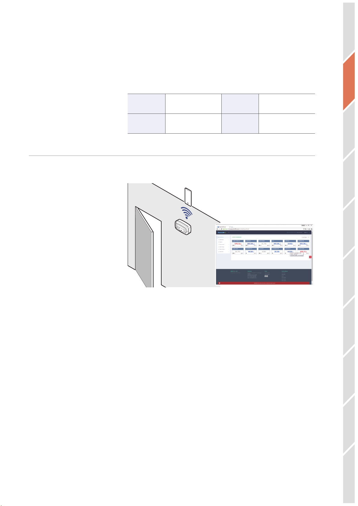
Introduction
The RADIONODE RN400-T2TS Data Logger periodically measures
temperature and RH, then sends measurement data to the Tapaculo®
365 server. The RN400-T2TS has a total of 4 I/O channels.
Channel 1 External Temp
sensor Channel 2 External Temp
sensor
Channel 3 External Temp
Sensor Channel4 External Temp
sensor
Key Features Key features of the RN400-T2TS include:
SW
POWER
ON/OFF
5BQBDVMPm
●Data Logger can be used with additional temp sensors.
●Use Wi-Fi connection to easily configure your Data Logger.
●Built-in buzzer that activates alarm when measurement is
outside the margin of error.
●Measurement data can be viewed remotely from Tapaculo 365
website. See Tapaculo 365 on page 34.
●Measurement data can be logged on a micro SD card.
Introduction

06
Installation Operation Configuration Tapaculo 365 Maintenance Customer Service
Information
HTTP Radionode
Protocol V2 Order ListAbout this Manual
Exterior
SW POWER
ON/OFF
2
3
4
1
5
❶ Display
❹ Power button
❷ Menu button
❺ Cable gland
❸ Display button
Power cables and cables of other devices, such as external sensors,
are connected via cable glands to the internal terminal block.
For instructions on how to use the buttons, see Operation on page
17.
Introduction

07
Installation Operation Configuration Tapaculo 365 Maintenance Customer Service
Information
HTTP Radionode
Protocol V2 Order ListAbout this Manual
Accessories All accessories, except for cable glands, are sold separately.
TC-K Temp Sensor
1.5 V Battery × 2
Cable Gland
3.6 V Battery DC Adapter (12 V, 500 mA)
TC-T Temp Sensor
In the event of power failure, two C-type 1.5 V batteries or one 3.6 V
battery must be placed in the Data Logger. RADIONODE Data Logger
is designed to not operate without a battery, even when external
power is connected.Use the same type of external temperature
sensor for one device. Type K Thermocouple (TC-K) and Type T
Thermocouple (TC-T) Sensor cannot be used together.
SW POWER
ON/OFF
5$,5$,
SW POWER
ON/OFF
5$5 5$5
SW POWER
ON/OFF
5$, 5$5
In the event of power failure, two C-type 1.5 V batteries or one 3.6 V
battery must be placed in the Data Logger. RADIONODE Data Logger
is designed to not operate without a battery, even when external
power is connected.
Only use Energizer®batteries. The Data Logger’s power
consumption varies significantly depending on operation
functions. Only Energizer batteries can keep performance
stable despite extreme battery usage fluctuations.
Introduction

08
Installation Operation Configuration Tapaculo 365 Maintenance Customer Service
Information
HTTP Radionode
Protocol V2 Order ListAbout this Manual
Specifications
SW
POWER
ON/OFF
165 mm
50 mm
100 mm
115 mm
RN400-T2TS Data Logger
External Temp
Sensor
Ch.1 TC- K/J/T/N/S/E/B/R
Ch.2 TC- K/J/T/N/S/E/B/R
Ch.3 TC- K/J/T/N/S/E/B/R
Ch.4 TC- K/J/T/N/S/E/B/R
Communication
2.4 GHz IEEE 802.11 b/g/n
WPA2-Enterprise
HTTP Get/Post
RS485 MODBUS RTU
Cable Gland PG-9
Water Resistance
Rating IP65 (IP67 is optional)
External DC power 5 - 30 V
Size 165 × 50 × 115mm
Operating conditions
-20 ~ 60 °C, 0 ~ 95% RH (non-condensed)
Note that the performance of the external temperature
sensor separately may differ from when it is connected
to the Data Logger.
Introduction

09
Installation Operation Configuration Tapaculo 365 Maintenance Customer Service
Information
HTTP Radionode
Protocol V2 Order ListAbout this Manual
Specifications
TC-K Temp Sensor
M. Range -20 ~ 300 °C (accuracy: ±0.8 °C)
Cable 3 m or 15 m
Size 55 mm, ⌀3.0
TC-T Temp Sensor
M. Range -100 ~ 200 °C (accuracy: ±0.8 °C)
Cable 3 m or 15 m
Size 55 mm, ⌀3.0
Note that the performance of the external temperature
sensor separately may differ from when it is connected
to the Data Logger.
Introduction

10
Introduction Operation Configuration Tapaculo 365 Maintenance Customer Service
Information
HTTP Radionode
Protocol V2 Order ListAbout this Manual Installation
Installation
The following procedure will guide from the installation procedure to
the Tapaculo 365 registration process.
1. Install sensors or connect other devices to the Data Logger as
needed.
2. Connect power and insert the battery.
3. Use the virtual Wi-Fi router feature to configure the Data Logger.
See Configuration on page 22.
4. Now that the Data Logger has been installed, it must be registered
to Tapaculo 365. See Tapaculo 365 on page 34.
Depending on your installation circumstances and conditions, your
installation process may vary. For example, if you are installing
multiple Data Loggers, you might find it easier to:
1. Insert batteries into all Data Loggers before running.
2. Configure one Data Logger first.
3. Use a micro SD card to set up additional Data Loggers. For this
method, see Memory Card Usage Configuration on page 32.
4. Register the Data Loggers onto Tapaculo 365.
5. Finally, install the Data Loggers.
Table des matières
Autres manuels Radionode Enregistreur de données


