Quackenbush 158QRA Series Manuel utilisateur
For additional product information visit our website at http://www.apextoolgroup.com
Service Manual
PL92-5000EN
05/14/2012
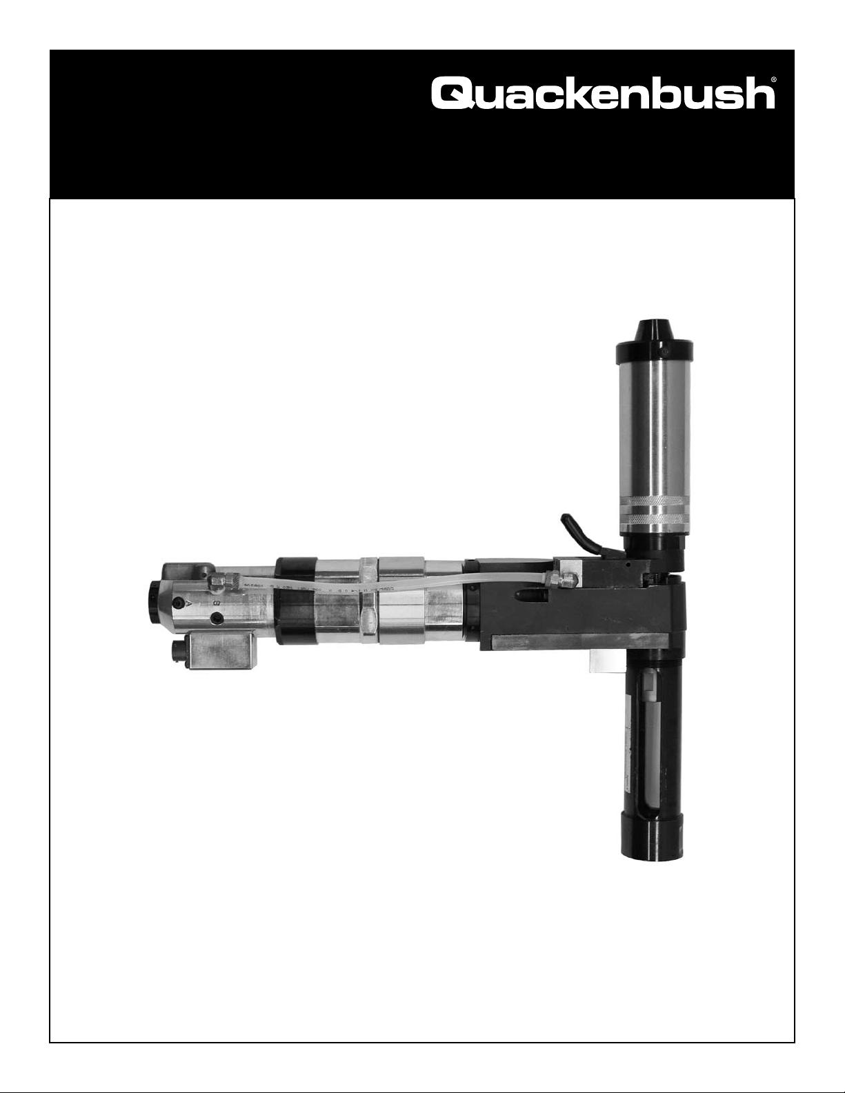
158QRA & 158/15QRA Series
Adaptive Positive Feed Drill

Page 2
PL92-5000EN
05/14/2012
XXX Q R A - XXX - XX - 9.50 X X - X XXX - XXX
Tool Series
158 = Positive Feed
158/15 = Positive Feed
Brand
Q = Quackenbush
Tool Style
R = Right Angle
Revision
A = Adaptive Drill
RPM (Spindle Speed)
Select Desired Speed
900 / 300 (158 series)
12/4 = 1200 / 400 (158/15 series)
Feed Rate
Select desired feed rate
10 = .001 IPR
20 = .002 IPR
Spindle Length
A =
Length (Specify 0.00) (Stroke+Non-Thread+Gear Head)
F = No Spindle
Spindle Interface Thread to Cutter
A = 1/4-28
B = 5/16-18
C = 3/8-24
D = 9/16-18
E = Other (specify)
Nose Attachment Thread
A = 2 1/4-20 (158 series)
B = 1 9/16-20 (158 series)
C = 1.0"-20 (158/15 series)
Options
2 =
Concentric Collet
4 = Indexer
5 = None
Accessories
A = Nose
B = Spindle
C = Chuck
D = Fluid Chuck
E = Fluid Inducer
F = None
Last three digits of material number
Quackenbush®
Model Nomenclature
Page 3
PL92-5000EN
05/14/2012
Language Version:
This Parts Manual is the “Original Instructions”
intended for all persons who will use or repair these
tools.
Product Identication:
Refer to the “Model Nomenclature” page in this
document.
Noise and Vibration:
Refer to documents CE-1009DC and CE-1009TD.
General Description:
Air powered right angle adaptive positive feed drill.
Intended Use:
These air powered adaptive feed drills are intended for
drilling holes. Use only for their designated purpose. Do
not use as a hammer, lever or other improper usage that
can cause tool damage and operator injury.
Copyright protection:
Apex Tool Group, LLC reserves the right to modify,
supplement or improve this document or the product
withoutpriornotice.Thisdocumentmaynotbereproduced
in any way, shape or form, in full or parts thereof, or
copied to another natural or machine readable language
or to a data carrier, whether electronic, mechanical,
optical or otherwise without the express permission of
Apex Tool Group, LLC.
General Safety Instructions:
These safety instructions must be accessible to the
operator at all times. They must be shown and made
available to all personnel involved in the use of this
equipment.
These safety instructions are not intended to be all
inclusive. Study and comply with all applicable Federal,
State and Local Regulations. If necessary, contact your
local Apex Tool Group representative for assistance.
Always disconnect the tool from the air supply before
adjusting or repairing.
Immediately shut off the tool in the case of unusual
sound or vibration. Have a qualied person check the
tool and repair before using.
Do not modify the tool, any guard or accessory unless
approved in writing by Apex Tool Group.
Implement and follow a Safety Maintenance Program to
provide inspection and maintenance of all phases of tool
operation and air supply equipment.
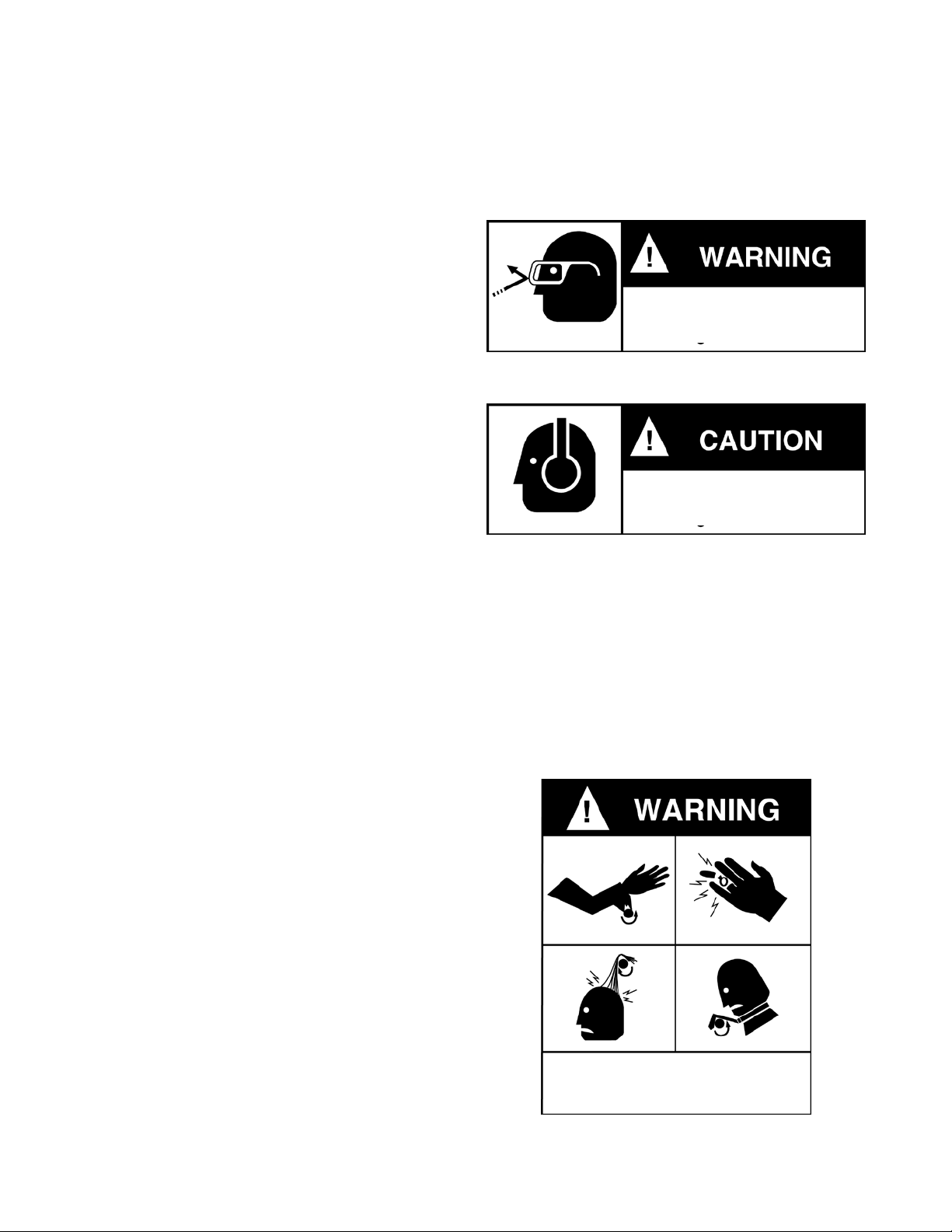
Eye Protection:
Hearing Protection:
Hearing protection is recommended in high noise areas,
85 dBA or greater. The operation of other tools and
equipment in the area, reective surfaces, process noises
and resonant structures can substantially contribute to
and increase the noise level in the area.
General Protection:
Follow good machine shop practices. Rotating shafts
and moving components can entangle or entrap and
may result in serious personal injuries. Never wear long
hair, loose tting clothes, gloves, ties or jewelry when
working with or near a drill of any type.
Quackenbush®
General Information and Safety
Impact resistant eye protection
must be worn when operating or
working near this tool.
Personal hearing protection is
recommended when operating or
working near this tool.
Do not wear loose tting clothes,
long hair, gloves, ties or jewelry when
operating or working near this tool.
Page 4
PL92-5000EN
05/14/2012
The spindle on right angle positive feed drills retracts at
a much faster rate than it feeds. Care must be taken to
avoid entrapment.
Nosepieces usually used with these drills are generally
slotted for visibility and access to chuck, cutter, and
retract stop adjustments. A spindle guard should be
used when operating the tool.
Spindle guards in one inch increments are available to
accommodate any length spindle. Slotted spindle guards
are available for tools with uid swivels.
Respirator:
Drilling or other use of this tool may produce hazardous
fumes and/or dust. To avoid adverse health effects utilize
adequate ventilation and wear a respirator if necessary.
Read the Material Safety Data Sheet (MSDS) for
any cutting uids or materials involved in the drilling
process.
Most dusts are combustible. See Material Safety•
Data Sheets for combustibility of a specic dust.
Non ferrous metal dusts are particularly hazardous.•
Examples: Aluminum, Magnesium, Titanium (Never
collect Magnesium in a dry dust collector.)
Never collect spark generating material in the same •
dust collector with combustible material. Examples:
Steel and Aluminum dust or Steel and Titanium
dust
Never use ammable nishing lubricants.•
Tool Operation:
This tool is designed to drill holes in different material
stacks and is for use only with the Quackenbush DMP
control box and should not be connected directly to a
standard air line.
Refer to PL92-DMP for operation and use of the DMP
control box, these instructions must be read and
understood before initiating any drilling operation.
The operating parameters for the tool are programmed
using the adaptive interface kit and DMP-TMS
programming software, refer to literature PL92-DMP-
PROG for details on programming the tool memory,
these instructions must be read and understood before
initiating any drilling operation.
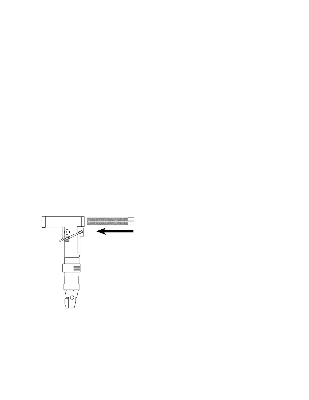
The power unit is started by turning the throttle valve
lever.
158 Gear Head: The feed mechanism is engaged by
depressing the feed cam knob while the tool is running.
158-15 Gear Head: The feed mechanism is engaged by
pushing the feed/retract lever (622973) down.
The spindle will automatically retract when the stop
collar depresses the retract lever. The spindle may be
manually retracted at any stage by pulling up on the
retract lever. The tool must be shut off when the spindle
is completely retracted.
158-15 Gear Head: The Gear Stop (622985) can be
adjusted by turning the two 1/8” hex set screws (867502)
on either side of the angle head.
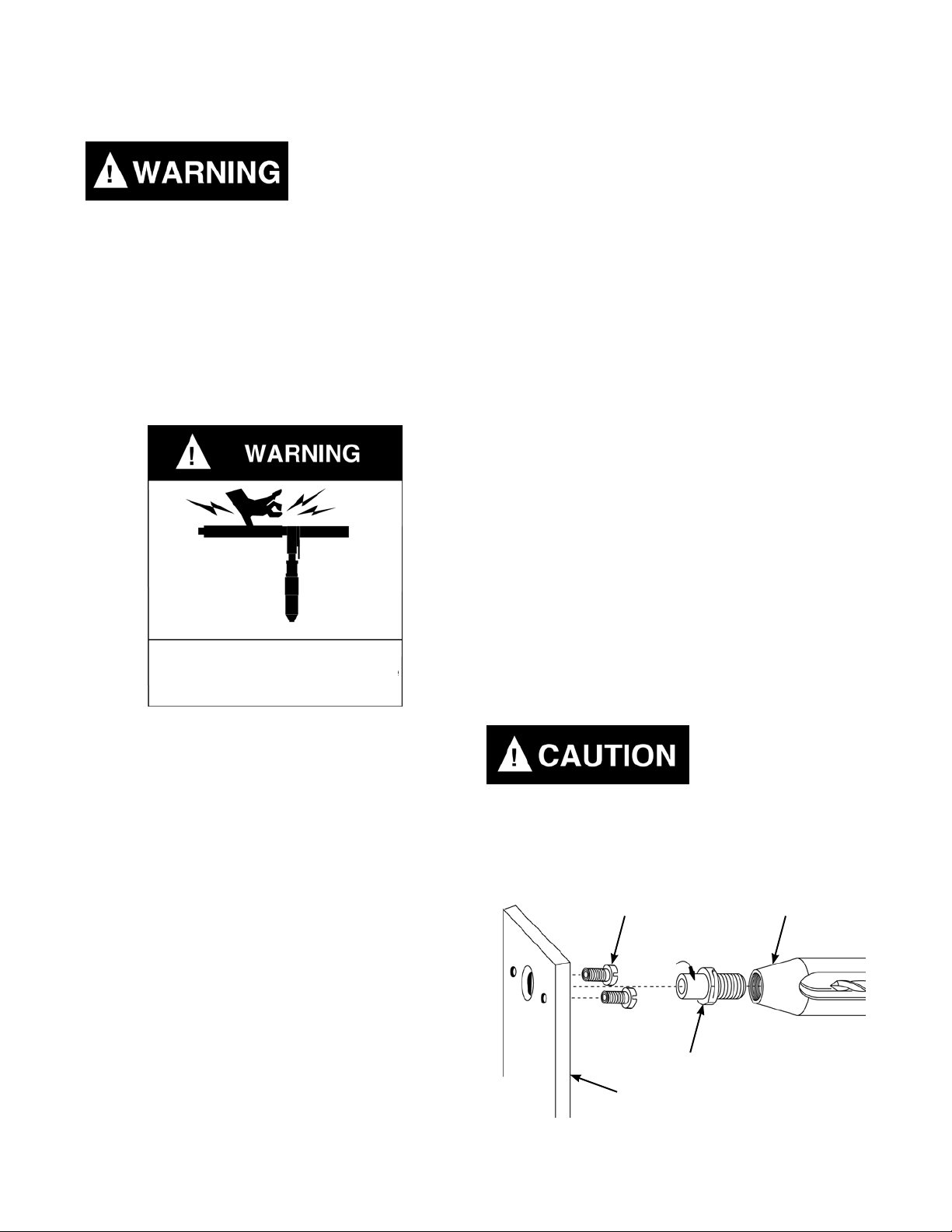
Always disconnect the tool from it’s air supply
before installing or removing a cutter and other
accessories or performing any maintenance.
Quackenbush®
General Safety and Tool Operation
Keep hands and ngers away from
slot in spindle guard and nosepiece
when handling or operating tool.
Lock Screws Tool Nose
Standard Threaded Drill Bushing
Tooling Fixture
Figure 1

Page 5
PL92-5000EN
05/14/2012
Warning Labels:
The warning labels on these tools are essential parts
of the product and are not to be removed. Check labels
regularly and replace any that are not clearly legible.
The Nosepiece safety label number is 202691.
Storage:
If it is necessary to store this tool for an extended period
of time (overnight, weekend, etc.), it should receive a
generous amount of lubricant at that time and again
when returned to service. Always store the tool in a
clean dry environment.
Torque Specications for Fasteners:
Basic engineering practice should be used when
assembling threaded components. Tightening torque
values are shown on the exploded views as a guide
for disassembly and re-assembly. The “Hand” image
indicates “Hand Tighten”.
Disassembly:
Remove the lock ring from the internal gear. Using a
suitable wrench, remove the internal gear (RH thread)
from the motor housing. The planet cage assembly
can now be removed from the internal gear and the
component parts disassembled.
158-15 Series: The drill head assembly utilizes a motor
adapter for assembly to the power unit.
Gearing:
Refer to Illustration “C”.
Gearing Disassembly:
Remove the lock ring from the internal gear. Using a
suitable wrench, remove the internal gear (RH thread)
from the motor housing. The planet cage assembly
can now be removed from the internal gear and the
component parts disassembled.
158 Series: Remove the bevel gear (RH thread) from
the planet cage to permit disassembly of the front planet
cage ball bearing and washer.
Assembly:
Apply a generous amount of No. 2 Moly grease to all
gearing components during assembly.
Assembly Note: Assemble the tang end of the planet
gear pins toward the front of the planet cage so the
planet cage washer will lock them in position, Figure 2.
Motor Module:
Refer to Illustrations “A” & “B”.
Motor Disassembly:
To remove the motor assembly from the motor housing
invert the tool in the vise. Remove the handle nut (RH
thread) and remove the handle assembly from the motor
housing. The complete motor assembly can now be
removed through the rear of the motor housing.
Remove the magnet rotor (LH thread) from the motor
shaft to permit disassembly of the rear bearing plate and
bearing.
Using a soft mallet, tap the motor shaft out of the front
ball bearing. This will allow the disassembly of the front
bearing plate, cylinder, rotor blades and rotor.
To remove the ball bearing from the front bearing plate,
remove the bearing retainer (LH thread) from the front
bearing plate.
Motor Assembly:
The rotor blades should be replaced during each
maintenance cycle or if they are worn 1/16” below the
rotor surface, Figure 3.
Assembly Note: The beveled edge of the blade is the
trailing edge. The rotor and cylinder have an “R” etched
on one end. The “R” should be facing the rear to insure
clockwise rotation, Figure 3.
Quackenbush®
Service Instructions
Planet Gear
Pin Tang
Figure 2
Planet
Cage
Figure 3
“R”
Toward
Air Inlet
1/16” Maximum
Rotor Blade
Beveled Edge
is Trailing Edge
Page 6
PL92-5000EN
05/14/2012
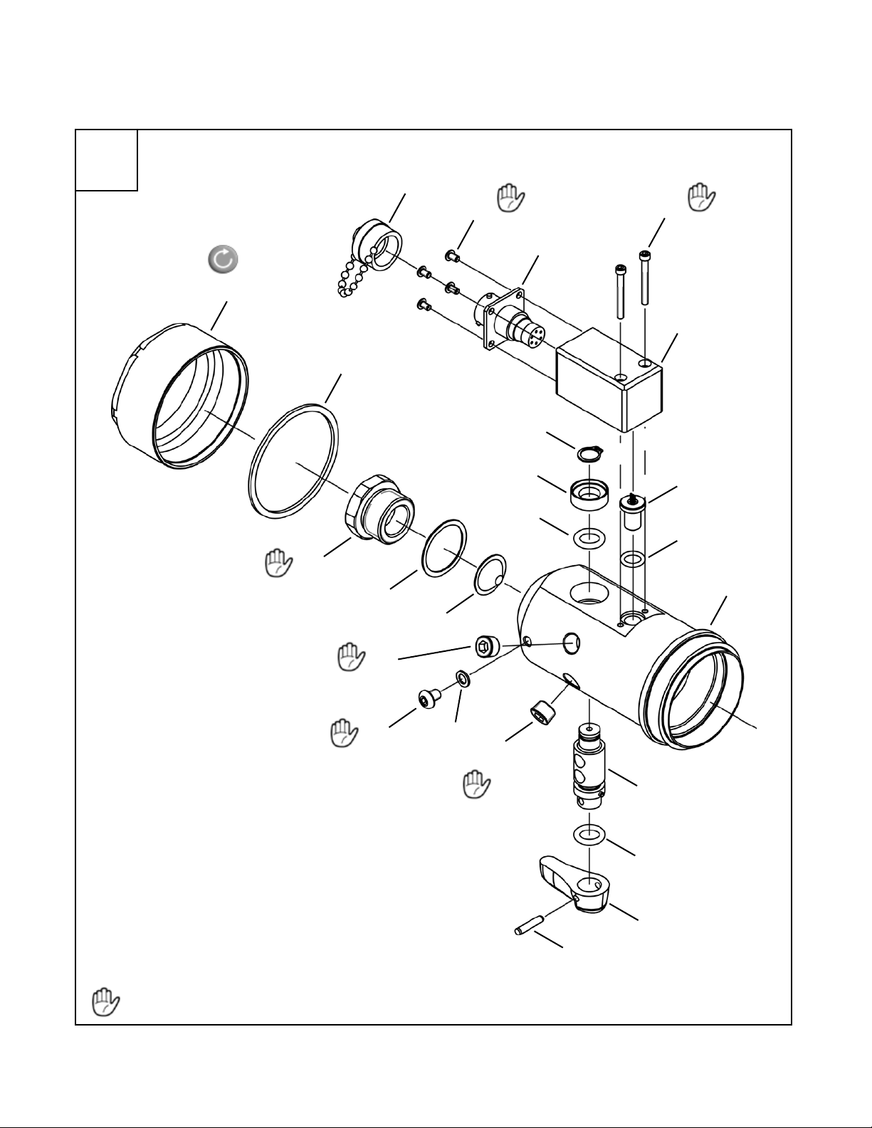
158 Drill Head:
Refer to Illustrations “D” & “E”.
158 Drill Head Disassembly:
Remove the stop body assembly (4 screws) from the
drill head housing.
Loosen the two set screws in the side of the housing and
remove the gear stop.
Remove the cylinder assembly (3 screws) from the drill
head housing.
Remove the housing cover (3 screws) from the drill
head housing. The gearing components can now be
disassembled as shown in Illustration “E”.
158 Drill Head Assembly:
Assemble the drill head in reverse order of disassembly.
Clean and inspect all parts for excessive wear or
damage and replace as necessary with Quackenbush
replacement parts.
Apply a generous amount of Acculube grease to all
gears and bearings during assembly.
Assembly Note: Always install the spindle from the drive
gear side of the drill head housing, Figure 4.
The 158 series drill head does not require shims to
set the bevel gears. Correct engagement of the bevel
gears is obtained by running the power unit at a very
slow speed and threading it into the drill head until gear
interference is felt. Back off the power unit approximately
1/8” turn or until there is no gear interference then tighten
the lock nut. This procedure will attain maximum gear
engagement.
After the tool is assembled, place a few drops of 10W
machine oil in the air inlet before attaching the air supply.
This will insure immediate lubrication of all parts as soon
as air is applied.
Gear Stop Adjustment:
There are two methods that can be used to adjust
the gear stop. The preferred method is to make the
adjustment during assembly of the drill before the retract
body and it’s related components are attached to the
drill head, see Method 1.
Method 1 (during assembly): Place the gear stop in
position with the two clutch rollers located on top of
the cam lobes, rather than in the detents. Turn the two
set screws, in the side of the housing, clockwise until
the springs begin to make up solid but are not crushed
or distorted. Now rotate the two set screws counter-
clockwise 90-180 degrees. With this method, it is easier
to determine when the spring makes up solid so there
is less tendency to force the screw in to deep causing
damage to the spring.
Method 2 (fully assembled unit): The clutch rollers are
normally sitting in the detents. Turn the two set screws,
in the side of the housing, clockwise until the springs just
begin to go solid. Care must be taken not to distort the
springs. Once the solid state is achieved, rotate the set
screws counter-clockwise 2-1/4 full turns plus 90-180
degrees. Important: Too much tension can result in
gear damage.
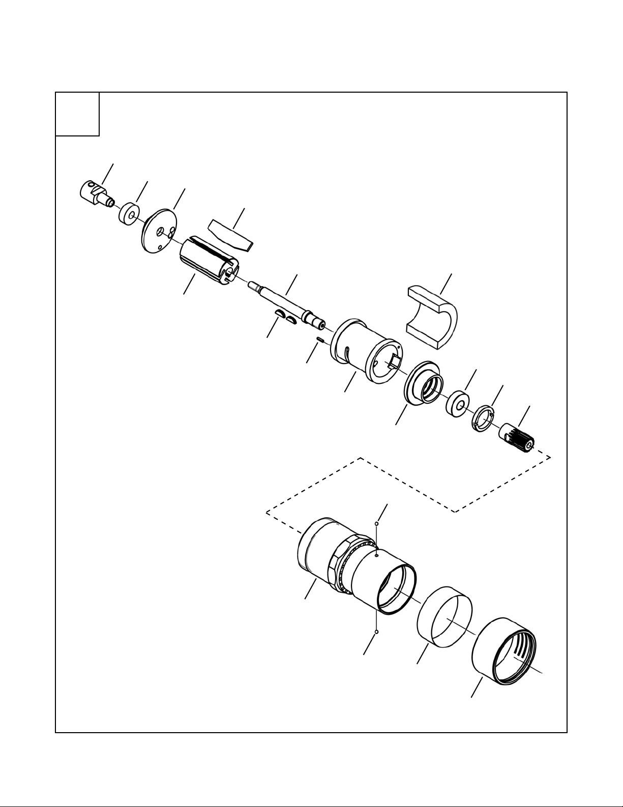
158-15 Drill Head:
Refer to Illustrations “F” & “G”.
158-15 Drill Head Disassembly:
Remove the motor adapter (LH thread) from the drill
head housing. Remove the hex drive adapter, drive
coupling, spacer, bearing, and bevel gear from the drill
head housing.
Remove the retract body assembly (4 screws) from the
drill head housing.
If used, remove the upper jam nut (LH thread) from the
spindle. Loosen the set screw in the side of the upper
stop collar and remove the stop collar (LH thread) from
the spindle.
Remove the nose adapter (LH thread) from the drill head
housing. The spindle assembly can now be removed
from the drill head housing.
Quackenbush®
Service Instructions
Figure 4
Install spindle from
this direction only.

Page 7
PL92-5000EN
05/14/2012
Remove the cover (2 screws) from the drill head housing.
The gearing components can now be disassembled as
shown in Illustration “G”.
158-15 Drill Head Assembly:
Assemble the drill head in reverse order of disassembly.
Clean and inspect all parts for excessive wear or
damage and replace as necessary with Quackenbush
replacement parts.
Apply a generous amount of Acculube grease to all
gears and bearings during assembly.
Assembly Note: When installing the 617168 ball bearing,
make sure the ball loading notches are facing the drill
head housing.
Assembly Note: Always install the spindle from the drive
gear side of the drill head housing, Figure 4.
Quackenbush®
Service Instructions
Page 8
PL92-5000EN
05/14/2012
Page 8
“A”
Hand Tighten: RH Thread
Ref.
Quackenbush®
Handle & Sensor Assemblies
20
19
16
18
15
16
14
11
12
13
6
8
6
7
10
3
9
17
1
2
3
4
5
2 in. lbs.
35-45 ft. lbs.

PL92-5000EN
05/14/2012
Page 9
EN
Description
-- 642014PT 1 Handle Assembly (includes Ref. 1 - 15)
1 642015PT 1 Throttle Handle (includes Ref. 6-8)
2 613254 1 Valve Assembly
3 844308 2 6 O-Ring
4 613697 1 1 Trigger
5 844111 1 2 Dowel Pin
6 843434 2 2 Pressure Plug
7 624121 1 3 Gasket
8 812962 1 3 Screw (10-32 UNF)
9 613253 1 Washer
10 812231 1 3 Retaining Ring
1 1 843656 1 3 Air Screen
12 1853 1 1 Shim
13 613102 1 Hose Adapter
14 613282 1 Clamp Ring
15 613283 1 Handle Nut
16 642013PT 1 Sensor Assembly (includes Ref. 16 - 20)
17 504970 1 3 O-Ring
18 622332 2 2 Screw (4-40 UNC)
19 202932 4 4 Screw (4-40 UNC)
20 633753PT 1 Protection Cap
(X) Recommended Spare Parts
Illustration "A"
(#) Quantity
Ref
Number
#
X
Quackenbush®
Handle & Sensor Assemblies
Page 10
PL92-5000EN
05/14/2012
“B” 642011PT Motor Module
18
Quackenbush®
Motor Module
17 16
15
14
12
13
11
10
8
5
7
6
9
4
3
42
1
Ce manuel convient aux modèles suivants
1
Table des matières
Autres manuels Quackenbush Percer

Quackenbush
Quackenbush 15QD Instructions d'installation et d'utilisation

Quackenbush
Quackenbush 230QGDAB Series Instructions d'installation et d'utilisation

Quackenbush
Quackenbush 120QP-21500 Series Manuel utilisateur

Quackenbush
Quackenbush 120SC - 225 Instructions d'installation et d'utilisation

Quackenbush
Quackenbush 230QGDA Series Guide rapide

Quackenbush
Quackenbush 15QNPD-D Instructions d'installation et d'utilisation


