
PTI security systems VP keypad controls entry Manuel utilisateur
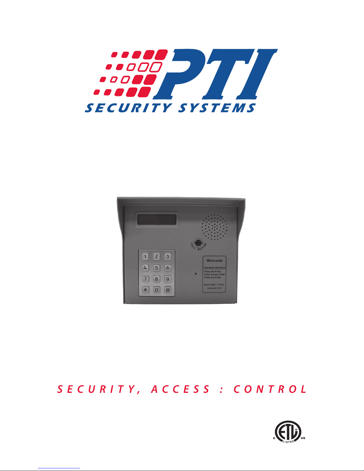
VP Keypad Access Device
Installation and Operation Manual
www.ptisecurity.com 800.331.6224
Revised April 2012

Thank you for purchasing the VP Keypad Access Device. While every
effort has been made to ensure the accuracy of the information in this
document, PTI Security Systems assumes no liability for any inaccuracies
contained herein. We reserve the right to change the information contained
herein at any time and without notice.
NOTE: This equipment has been tested and found to comply with the limits for
a Class B digital device, pursuant to Part 15 of the FCC Rules. These limits are
designed to provide reasonable protection against harmful interference in a
residential installation. This equipment generates, uses, and can radiate radio
frequency energy and, if not installed and used in accordance with the instructions,
may cause harmful interference to radio communications. However, there is
no guarantee that interference will not occur in a particular installation. If this
equipment does cause harmful interference to radio or television reception, which
can be determined by turning the equipment off and on, the user is encouraged to
try to correct the interference by one or more of the following measures:
Reorient or relocate the receiving antenna.
Increase the separation between the equipment and receiver.
Connect the equipment into an outlet on a circuit different from that to which the
receiver is connected.
Consult the dealer or an experienced radio TV technician for help.
This Class B digital apparatus complies with Canadian ICES-003.
Cet appareil numérique de la classe B est conforme à la norme NMB-003 du
Canada.
© 2012 PTI Security Systems
All rights reserved. No part of this publication may be reproduced,
transmitted, transcribed, or translated into any language in any form, by
any means, without written permission of PTI Security Systems.
114A3868
This equipment generates, uses, and can radiate radio
frequency energy and if not installed and used in accordance
with the instruction manual, may cause interference to radio
communications. It has been tested and found to comply with the limits
for a Class A computing device pursuant to Subpart J of Part 15 of FCC
rules, which are designed to provide reasonable protection against such
interference when operated in a commercial environment. Operation of
this equipment in a residential area is likely to cause interference in which
case the user, at his/her own expense, will be required to take whatever
measures may be required to correct the interference.
With the RS485 communication scheme, a keypad can be located
as far as 4000 feet from the controller, which is why shielded twisted
pair cable with ground wire is required for optimal operation.
Voltage drops across long lengths of wire must also be considered. The
farther the device is from the controller, the larger the gauge of wire that
must be used. Refer to the Voltage Drop Calculation QuickDoc for more
information. This document is available on our web site at www.ptiaccess.
com/downloads.
THE SYSTEM WILL NOT OPERATE PROPERLY IF THE
VOLTAGE IS BELOW 12VDC.Extreme care should be taken
when choosing a power supply voltage and current rating. Long
distance runs may require a remote power supply to be installed in line
with an RB5 relay to ensure proper operation.

1
Contents
Technical Specications: .......................................................................... 1
Installation ................................................................................................ 2
Mounting Options ................................................................................ 2
Drive Up Accessibility ...................................................................... 2
Walk Up Accessibility ....................................................................... 2
ADA Guidelines for Access Control ..................................................... 3
Recommendations for Sites ............................................................ 3
Mounting Access Devices ................................................................... 6
Surface Mount ................................................................................ 6
Gooseneck Stand Mount ................................................................. 6
Wall Mount Gooseneck.................................................................... 7
Keypad Adapter Plate ...................................................................... 7
Single Bollard................................................................................... 8
Double Bollard ................................................................................. 8
Installing VP Series Keypads............................................................... 9
Testing the Keypad ............................................................................ 16
Operation................................................................................................ 17
VP Keypad Setup Function................................................................ 17
Setup Parameters/Functions ......................................................... 17
Standard Display Messages .............................................................. 20
Access Codes and Cards .............................................................. 20
Security Checks............................................................................. 21
Access Response Messages......................................................... 23
System Maintenance.............................................................................. 24
Periodic Visual Inspection.................................................................. 24
Periodic Cleaning............................................................................... 24
Cleaning the Housing and Touchpad............................................. 24
Cleaning the Magnetic Stripe Reader................................................ 24
Troubleshooting ..................................................................................... 25
Test power and communication ......................................................... 25
Test card and code input.................................................................... 27
Test individual devices ....................................................................... 28
Test multiple devices or entire site..................................................... 29
Warranty & Disclaimer ........................................................................... 31

1
teChniCal speCifiCations:
Power Supply:
Voltage: 12 – 18 VDC or AC
Current Consumption: 300mA Maximum
Relay Outputs (resistive load):
Maximum Switching Voltage: 30 VAC/DC
Maximum Switching Current: AC: 10 A (NO) / 3 A (NC)
DC: 5 A (NO) / 3 A (NC)
Maximum Switching Capacity: 1250 VA (NO)
375 VA (NC)
Minimum Permissible Load: 10 mA at 5VDC
Contact Resistance: 100 mΩ Maximum
Life Expectancy:
Mechanical: 10,000,000 operations
Electrical: 200,000 operations minimum
(at maximum rated load)
Environmental:
Ambient Temperature: -40°C to +80°C (-40°F to 176°F)
Ambient Humidity: 0% to 100%
Note: The humidity inside the housing for any VP device cannot exceed
100% and must be noncondensing.
3
2
installation
MOUNTING OPTIONS
The VP keypad controls entry to or exit from a secured area. It works in
conjunction with a controller and control software. The VP can be used
to control gate access, building access, room access, elevator access,
etc. It is designed for ease of use and exibility. Both the keypad and the
large LCD are backlit for easy visibility day and night. Mounting height for
devices will vary with local code regarding handicap access, emergency
and re access, and other regulations.
Before installing the VP, determine where and how the device will be
installed as the mounting location will be determined by how the device is
to be used. If it is to be used for drive up access, it must be installed where
it can be accessed from a vehicle’s driver door. If it is to be used for walk up
access, it must be installed where it is easily accessible to a person on foot.
Drive Up Accessibility
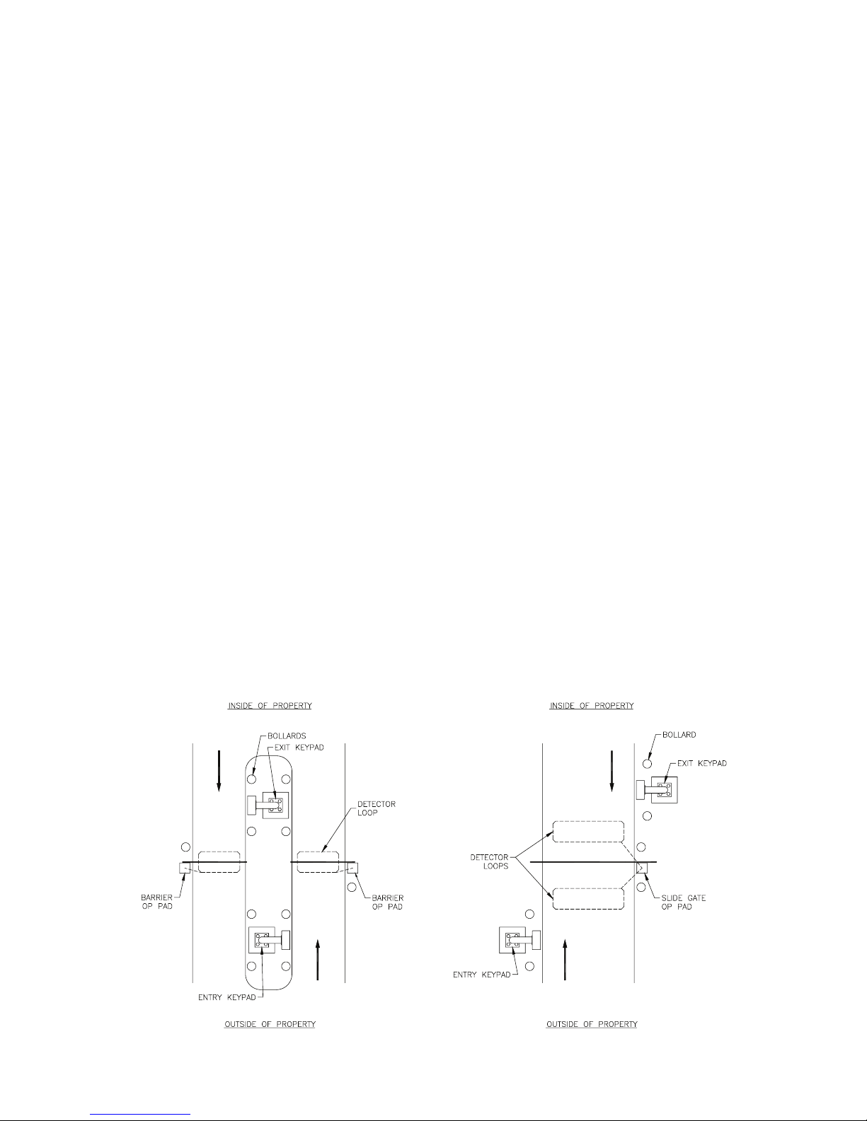
When the VP will be positioned for drive up accessibility, the device must
be mounted within easy reach of the driver of an automobile or light truck.
Most such applications use gooseneck stands that are located on an island
between the entry and exit gates, or to the left side of the gate if a single
gate is used. Local building codes may set a minimum and maximum
height for devices that are accessible by vehicle. Figure 1 shows possible
mounting locations when used for vehicle access.
Walk Up Accessibility
When the VP is used for walk up access, it can be mounted on a stand
or attached to a wall. It can be surface mounted so that it protrudes from
the wall.
Figure 1

3
ADA Guidelines for Access Control
The Americans with Disabilities Act of 1990 (ADA) prohibits discrimination
in and ensures equal access to employment, government services, public
accommodations, transportation, and commercial facilities for persons with
disabilities. Some of the guidelines and requirements from this law can be
applied to access control. Because many local municipalities have much
stricter standards than the ADA, we strongly recommend that owners,
builders, and installers consult a qualied expert in local, state, and federal
interpretations of ADA and similar laws. For more information about the
ADA, visit the ADA web site at www.ada.gov or the Department of Justice
ADA web site at www.usdoj.gov/crt/ada/ or call the ADA Information Line
at (800) 514-0301. Many communities have adopted the Americans with
Disabilities Act (ADA) as the standard for locating devices that the general
public will use.
Recommendations for Sites
The ADA and other similar laws are open to some degree of interpretation
by local authorities and courts. It is in your best interest to familiarize
yourself with the complete requirements for ADA and other similar local
laws. Most important, however, is to work to provide reasonable access to
your services by persons of all abilities. Below are some recommendations
that may help.
• Contact a local inspector or architect who can provide assistance in
designing the access to your facility with respect to ADA and other
similar laws
• Visit the ADA web site or call the information line listed above
• Provide adequate, well-lit signs (written, picture, and Braille)
• Design hallways with adequate room for wheelchairs
• Provide adequate access to all keypads, access devices, and
elevator controls as provided for in ADA
• Use keypads with proximity cards or key fobs and audible signals to
provide greater access exibility
5
4
ADA Mounting Requirements
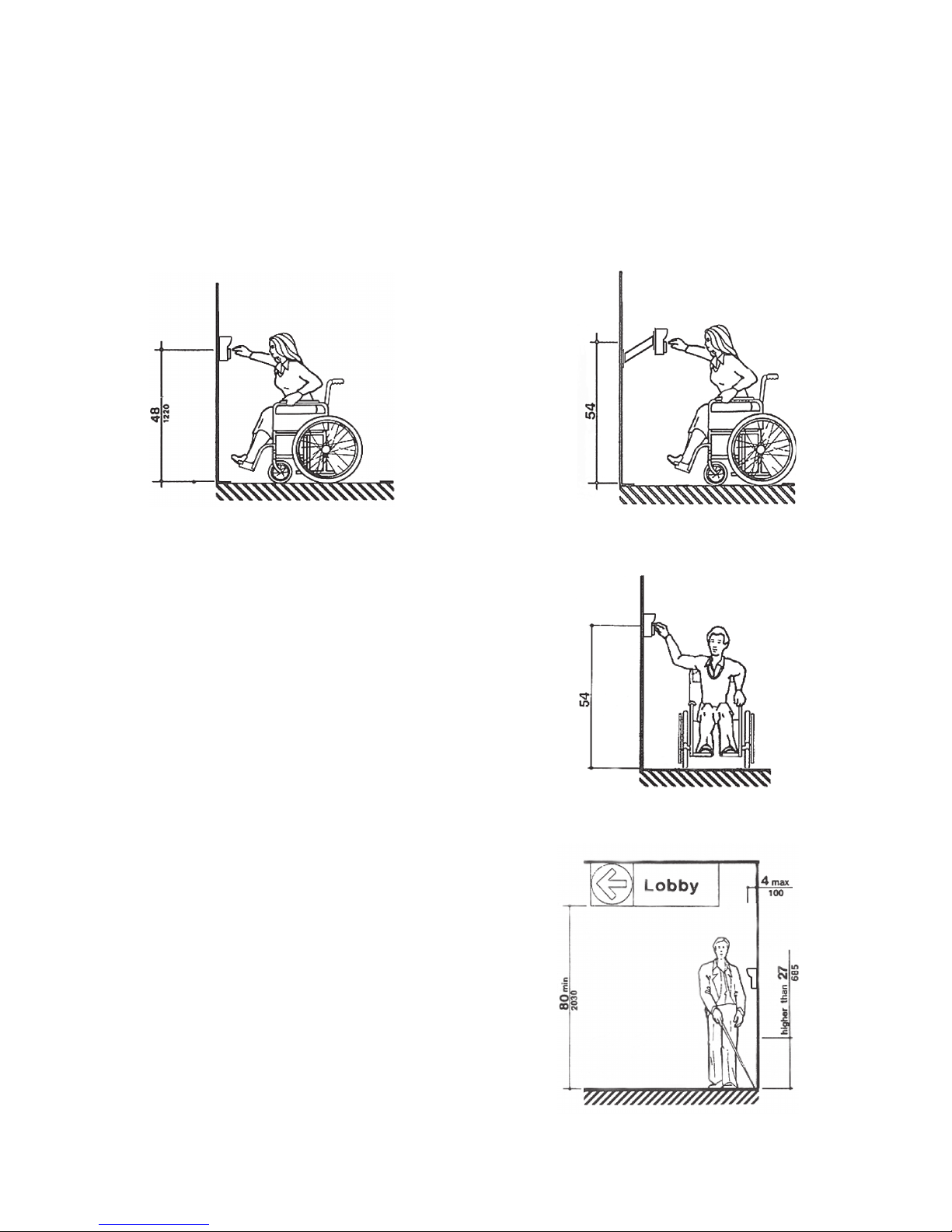
1. Keypads should be mounted so that the top of the number
touchpad is no more than 48 inches above the nished oor with
no obstructions in locations where wheelchair access is available
only from the front. Keypads can be placed higher if a wall mount
gooseneck allows closer access to the keypad.
2. Keypads should be mounted so that the
top of the number touchpad is no more
than 54 inches above the nished oor
with no obstructions in locations where
the wheelchair has sideways access.
3. Keypads should be mounted so as not
to protrude more than 4 inches from
the wall. If mounted in a bollard or
pylon, it may protrude up to 12 inches.
Items mounted higher on the wall or
ceiling must be 80 inches or higher
above the nished oor.
Figure 2a Figure 2b
Figure 3
Figure 4
5
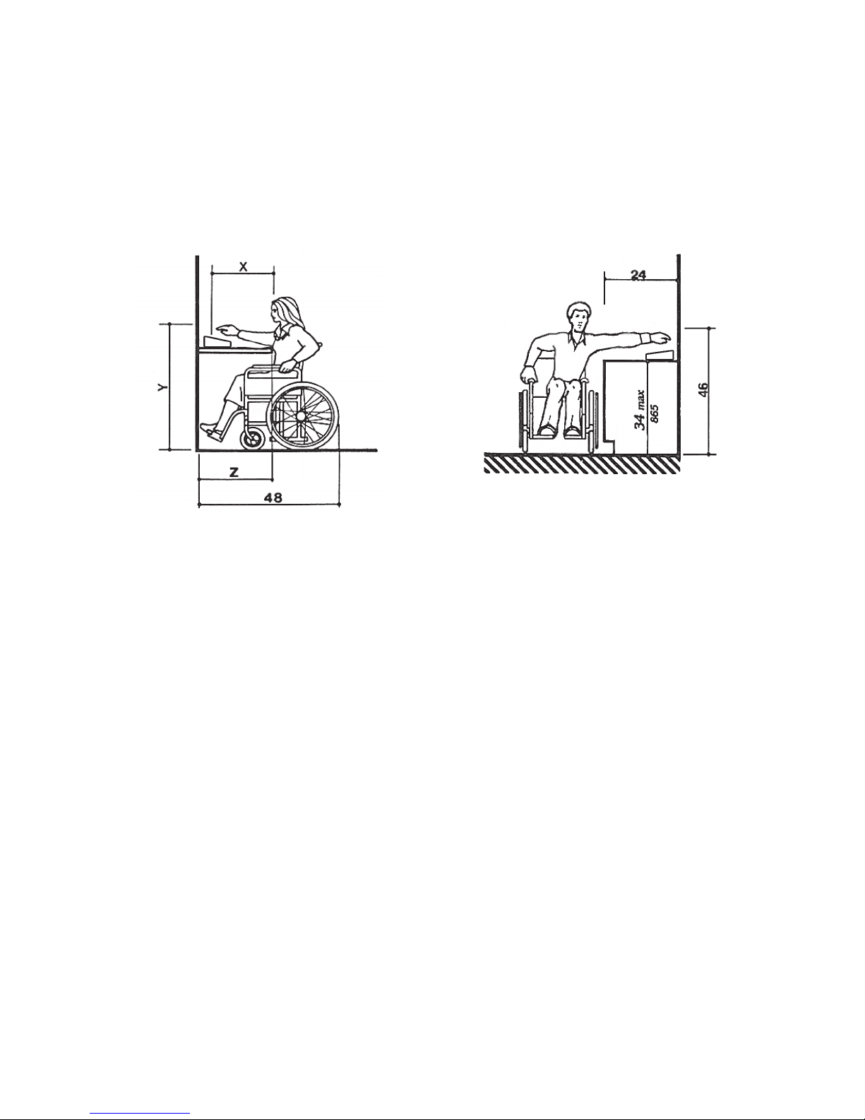
4. Computer keyboards and other ofce equipment should be placed
on desks between 28” – 34” tall with no more than 20 inches in
reach depth for obstructed front access or 24 inches in reach depth
for obstructed side reach access. In the rst gure below, if X < 20”
then Y = 48”. When X = 20” – 25”, then Y = 44”. X should always be
≤ 25”.
All information contained herein is from the ADA web site and the Department
of Justice Code of Federal Regulations Excerpt CFR Part 36 ADA Standards
for Accessible Design revised July 1, 1994. PTI Security Systems is not liable
for the information contained in this document and we strongly recommend that
installers, owners, and builders work with qualied experts in the local, state, and
federal interpretations of ADA and other similar laws. Refer to the ADA Standards
for Accessible Design and Federal regulations for more specic information and
requirements.
Figure 5a
Figure 5b
7
6
Mounting Access Devices
The proper mounting height for the VP varies with the application. There
are several options for mounting access devices: surface mount and wall
mount. These can be attached to a wall or installed at an entrance using
a gooseneck or bollard.
Once it has been determined where to install the keypad, the location and
purpose of the device should be noted on a site security wiring plan that is
kept in a safe location for future maintenance and service purposes.
Surface Mount
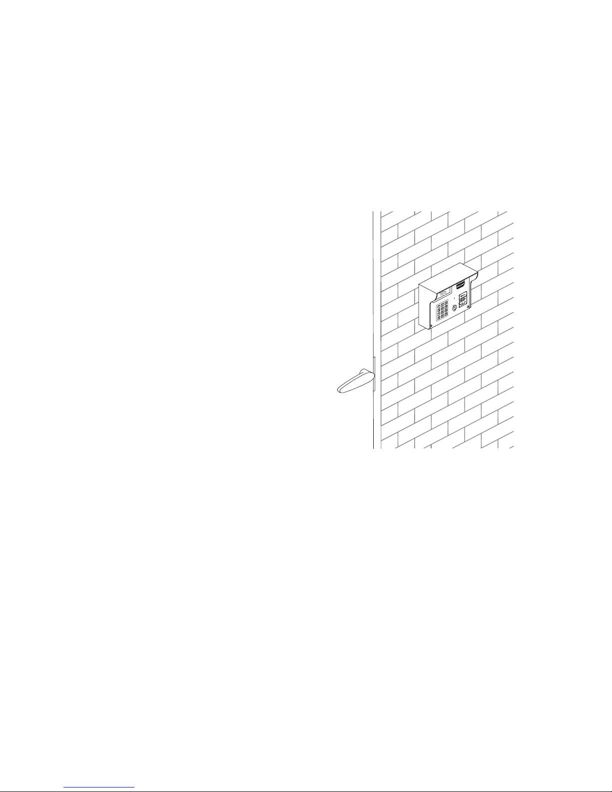
Surface mounting of keypads is
generally used in conjunction with door
strikes and elevators. Mounting height
is generally 48” – 58” from the nished
oor to the center of the ‘5’ button on
the touchpad. The actual location of
the keypad may be affected by local
building codes.
The type of fasteners required will
depend on the material used to
construct the wall. If the VP is installed
on an exterior wall, make sure the
contact point between the housing and
the wall is sealed with some form of
silicone sealant rated for outdoor use
to prevent moisture and insects from
getting into the housing.
Gooseneck Stand Mount
A gooseneck is commonly used for driveways for vehicle access. The
gooseneck can also be used near doors for wheelchair access or when
sidewalks and landscaping require a freestanding keypad mount away
from the building.
The base plate is equipped with a hole that will accept conduit (¾”
maximum) for the electrical wiring. Ensure the conduit is placed properly
and the wiring is run through the conduit before mounting the gooseneck
stand to the concrete base. The actual location of the gooseneck and the
mounting techniques may be affected by local building codes. Generally,
the keypad should be protected with concrete bollards that prevent
vehicles from hitting the keypad.
There are several different styles of gooseneck stands available. See
Figure 6 for the dimensions of two common styles.
Figure 6
Table des matières
Autres manuels PTI security systems Clavier


